Three-optical-path signal compensation system in optical MEMS accelerometer and method thereof

An accelerometer and signal compensation technology, applied in the direction of measurement of acceleration, velocity/acceleration/shock measurement, measurement device, etc., can solve the problems of limiting displacement measurement accuracy, acceleration measurement accuracy, increasing the cost of optical MEMS accelerometer, and output signal disturbance, etc. Achieve the effect of improving zero bias stability, convenient connection and integration, and low cost

Active Publication Date: 2015-12-23
ZHEJIANG UNIV
View PDF4 Cites 14 Cited by
  • Summary
  • Abstract
  • Description
  • Claims
  • Application Information

AI Technical Summary

Problems solved by technology

The laser in the optical MEMS accelerometer has power fluctuations and frequency fluctuations. In the actual measurement process, frequency fluctuations will introduce phase errors in the interference field, thereby affecting the measured displacement and acceleration values. For this error, you can choose a stable The power fluctuation of the laser itself will directly cause the disturbance of the output signal. The power fluctuation of the common laser is on the order of 1%. Choosing a laser with high power stability will greatly increase the cost of the optical MEMS accelerometer
Since the current optical MEMS accelerometer takes the input laser light intensity as a fixed value when calculating the input acceleration value, the existence of power fluctuations in the laser light source itself will introduce calculation errors, which limit the improvement of displacement measurement accuracy and acceleration measurement accuracy.
Moreover, the ambient light and stray light in the actual measurement environment will also disturb the output signal and affect the measurement results. When the accuracy of the optical displacement measurement system reaches the nanometer level, these effects cannot be ignored

Method used


Image

  • Three-optical-path signal compensation system in optical MEMS accelerometer and method thereof
  • Three-optical-path signal compensation system in optical MEMS accelerometer and method thereof
  • Three-optical-path signal compensation system in optical MEMS accelerometer and method thereof

Examples


Embodiment Construction

[0038] The implementation method of the present invention for completing signal compensation and correction will be described in detail below in conjunction with the accompanying drawings.

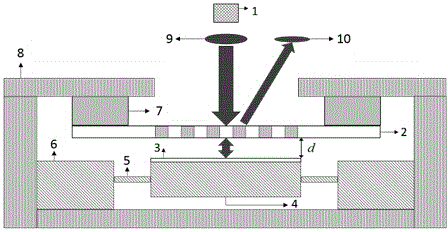
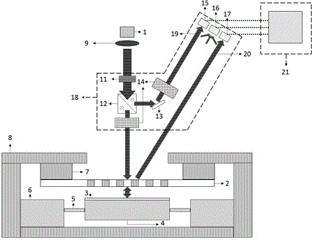
[0039] The three optical path signal compensation system and compensation method provided by the present invention are applied to an optical MEMS accelerometer, the purpose is to reduce the output signal disturbance caused by the power of the laser light source itself and the ambient light, thereby improving the stability of zero bias and acceleration measurement accuracy. Such as figure 1 As shown, the optical MEMS accelerometer includes a VCSEL laser 1, a diffraction grating 2, a reflector 3 composed of metal coated on the upper surface of the proof mass, a sensitive mass 4, a cantilever beam 5, a substrate 6, a piezoelectric ceramic 7 and a package shell8. The laser 1 is used to provide a 670nm laser beam 9 for measurement, and the first-order diffraction interference signal light 10 ...


PUM


Abstract

The invention discloses a three-optical-path signal compensation system in an optical MEMS accelerometer and a method thereof. The three-optical-path signal compensation system comprises a three-optical-path compensation optical path and a signal processing system, wherein the three-optical-path compensation optical path comprises an optical isolator, a miniature beam splitter prism, a plane mirror, an adjustable attenuator and an photoelectric detector; and the compensation signal processing system comprises three analog-to-digital (AD) conversion modules, a subtracter, a divider, a data storage, summation and average module and multiplier, and the modules are realized through a programmable digital signal processor. The three-optical-path signal compensation system is relatively simple in structure, and can effectively reduce influences imposed on output signals by power fluctuation of a light source and ambient light. Compared with a scheme of adopting a laser with extremely high power stability, the cost of the optical MEMS accelerometer can be effectively reduced. In addition, the system and the method disclosed by the invention can be effectively applied to the optical MEMS accelerometer, disturbance of the output signals is reduced, and finally the zero-bias stability and the precision of accelerometer measurement are improved.

Description

technical field [0001] The invention relates to a signal compensation system and method in an accelerometer, in particular to a three-light path signal compensation system and a compensation method for suppressing signal disturbance caused by power fluctuations of the light source itself and ambient light in an optical MEMS accelerometer. Background technique [0002] The accelerometer is a sensor that measures the acceleration of an object. Its basic measurement principle is based on Newton’s second theorem. The accelerometer converts the acceleration into the displacement of the mass block in the elastic structure. The displacement has a definite relationship with the input acceleration. The magnitude of the input acceleration can be obtained by measuring the displacement. Therefore, the accelerometer usually includes a mechanical acceleration sensitive system and a displacement measurement system, and the measurement sensitivity of the acceleration and the noise of the ac...

Claims


Application Information

Patent Timeline
Patent Type & Authority Applications(China)
IPC IPC(8): G01P15/093
Inventor 卢乾波娄树旗焦旭芬白剑
Owner ZHEJIANG UNIV
Why Eureka
Try Eureka