Hot-rolled copper plate

A copper plate and pure copper technology, applied in the direction of metal rolling, conductors, rods/rods/wires/strip conductors, etc., can solve the problems of large number of processes, high manufacturing costs, suppression of residual stress of copper plates, etc., and achieve machinability and excellent fatigue characteristics, the effect of suppressing abnormal discharge

A copper plate and pure copper technology, applied in the direction of metal rolling, conductors, rods/rods/wires/strip conductors, etc., can solve the problems of large number of processes, high manufacturing costs, suppression of residual stress of copper plates, etc., and achieve machinability and excellent fatigue characteristics, the effect of suppressing abnormal discharge

CN105189792AActive Publication Date: 2015-12-23MITSUBISHI MATERIALS CORP

Image

  • Hot-rolled copper plate
  • Hot-rolled copper plate
  • Hot-rolled copper plate

Examples


Embodiment

[0074] Hereinafter, the result of the evaluation test which evaluated the function effect of the hot-rolled copper sheet which concerns on this invention is demonstrated.

[0075]

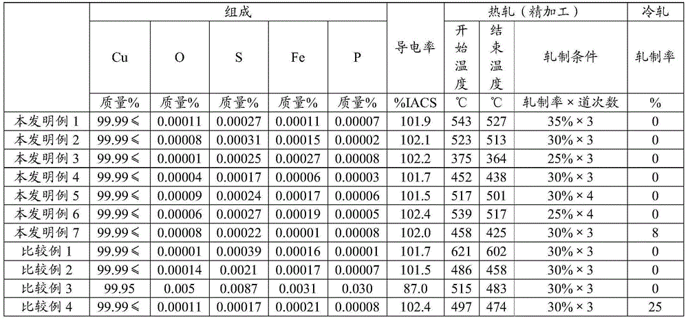
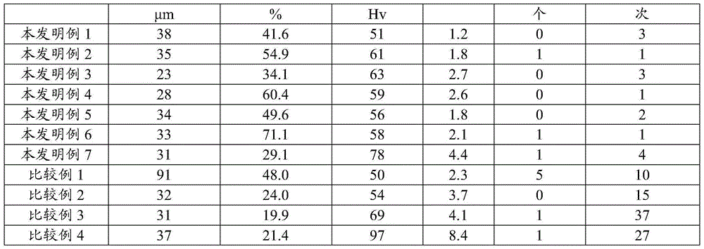
[0076] As a rolling material, a cast ingot of oxygen-free copper (purity: 99.99% by mass or more) for electron tubes was used. The raw material size before rolling was 620 mm in width x 900 mm in length x 250 mm in thickness, and hot rolling was performed to produce the hot-rolled copper plate described in Table 1. The total rolling reduction in the hot rolling process was set to 92%. In addition, Table 1 shows the start temperature and end temperature of the finish hot rolling in the rolling in the final stage of the hot rolling process, that is, the finish hot rolling. Temperature measurement was performed by measuring the surface temperature of the rolled sheet with a radiation thermometer. Then, after completion of such hot rolling, cooling is performed by water cooling at a cooling rate of...


PUM

PropertyMeasurementUnit
particle diameteraaaaaaaaaa

Abstract

This hot-rolled copper plate is made from pure copper having a purity of 99.99 mass% or greater, the average crystal grain diameter being 40 microns or less, and the (Sigma 3+Sigma 9) grain boundary length ratio (L(sigma 3 + sigma 9) / L), which is the ratio between the total crystal grain boundary length (L) measured by the EBSD method and the sum (L(sigma 3 + sigma 9)) of the Sigma 3 grain boundary length (L sigma 3) and the Sigma 9 grain boundary length (L sigma 9) is 28% or greater.

Description

technical field [0001] The present invention relates to a tube plate suitable for use in sputtering targets, backing plates, Steve molds (Stevemold), electron tubes for accelerators, magnetrons, superconducting stabilization materials, heat dissipation substrates, vacuum components, and heat exchangers. Hot-rolled copper sheets for copper processed products such as bars, electrode materials, and anodes for electroplating. [0002] This application claims priority based on Patent Application No. 2013-080844 for which it applied in Japan on April 8, 2013, and uses the content here. Background technique [0003] Conventionally, as a copper plate made of pure copper used in the above-mentioned copper processed products, it is generally manufactured through the steps of casting an ingot of pure copper and hot working (hot rolling or hot forging) of the ingot. The hot working process, the cold working process of cold working (cold rolling or cold forging), and the heat treatment ...

Claims


Application Information

Patent Timeline
23 Dec 2015
Publication
CN105189792A
IPC
C22C9/00; B21B3/00; C22F1/08; C23C14/34; H01B1/02; H01B5/02; C22F1/00
CPC
C22C9/00; C22F1/00; C22F1/08; C23C14/3414; H01B1/026
Inventors
牧一诚; 森广行