Method and apparatus for attaching a circuit component

A technology of electrical components, components, applied in the field of attaching circuit components

Inactive Publication Date: 2015-12-23
KELSEY HAYES CO
View PDF4 Cites 2 Cited by
  • Summary
  • Abstract
  • Description
  • Claims
  • Application Information

AI Technical Summary

Problems solved by technology

[0006] Although known soldering techniques have proven useful and reliable, each technique requires special equipment to make the required physical and electrical connections

Method used


Image

  • Method and apparatus for attaching a circuit component
  • Method and apparatus for attaching a circuit component
  • Method and apparatus for attaching a circuit component

Examples


Embodiment Construction

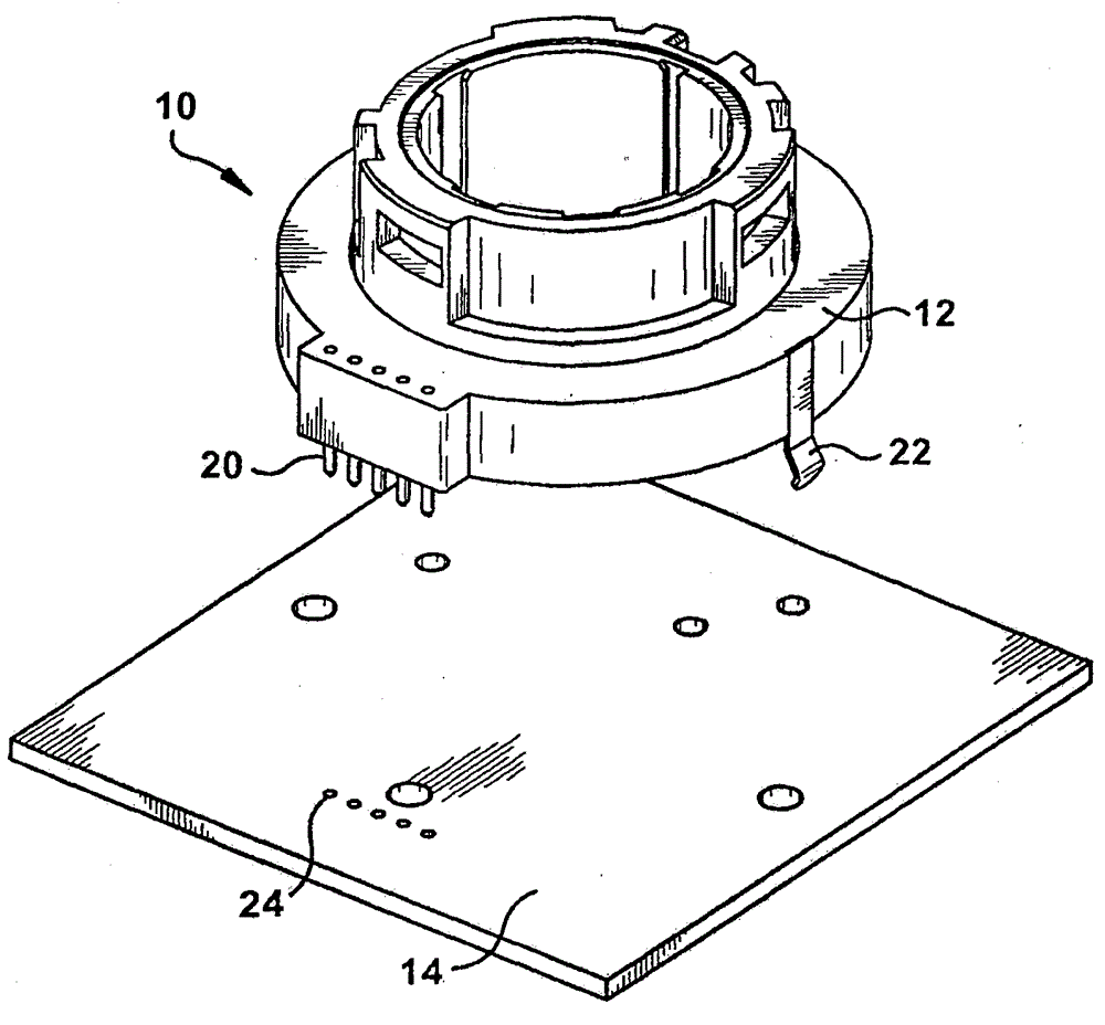
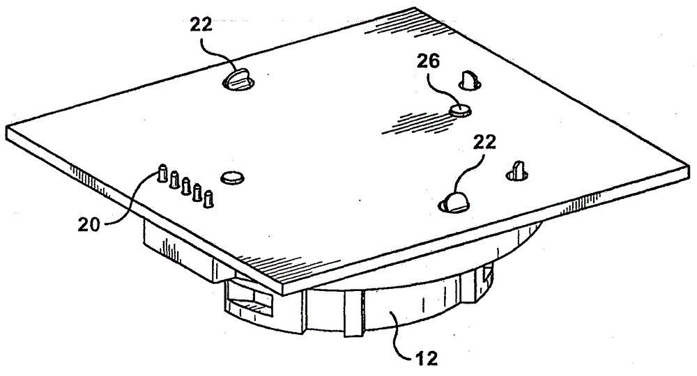
[0022] Referring to Figures 1 and 2, a known mounting configuration 10 between an electrical component 12 and a PCB 14 is shown. Electrical component 12 may be a rotary type potentiometer (eg, a temperature selection dial for a vehicle heating / ventilating / air conditioning system) having a plurality of electrical leads or terminals 20 and alignment and securing tabs 22 . PCB 14 includes a plurality of plated through holes 24 adapted to receive terminals 20 when electrical component 12 is placed on PCB 14 . Two resilient alignment and securing tabs 22 snap into corresponding plated through holes on PCB 14, also mechanically securing electrical component 12 to PCB 14 prior to soldering. Additional alignment pins 26 (see FIG. 2 ) may be provided on the electrical component 12 to be received through additional mounting and alignment holes on the PCB 14 .

[0023] Once mounted to the PCB 14, the electrical component has its own electrical pins 20 which are soldered to plated throug...


PUM


Abstract

Method and apparatus for attaching an electrical component to a printed circuit board. The apparatus includes a circuit board, an elastomeric connector, a rotary electrical component having a connector housing for holding the elastomeric connector, and one or more fasteners for securing the electrical component to the circuit board with sufficient force to compress the elastomeric connector and thereby ensure electrical contact between the electrical component and the printed circuit board.

Description

[0001] Cross References to Related Applications [0002] This application claims priority to U.S. Provisional Application Serial No. 61 / 808,814, filed April 05, 2013, entitled "Method and Apparatus for Attaching Circuit Components (method and apparatus for attaching a circuit component)," Attorney's Docket No. BCS-022142USPRO rights and interests. The above provisional application is hereby incorporated by reference in its entirety for all purposes. technical field [0003] The present invention relates to a method and apparatus for attaching a circuit component, such as a rotary potentiometer, to a printed circuit board ("PCB"). Background technique [0004] Attaching the circuit component to the PCB is generally done by inserting the leads of the circuit component into plated-through holes on the PCB and then soldering the component in place. One technique known for attachment and soldering in production is wave soldering. In mass wave soldering, the electrical componen...

Claims


Application Information

Patent Timeline
Patent Type & Authority Applications(China)
IPC IPC(8): H01C10/32
CPCH01C10/46H01C1/01H01C10/34H05K3/303H05K13/046
Inventor G·派珀J·海德T·瑞德塞尔
Owner KELSEY HAYES CO
Why Eureka
Try Eureka