Centrifuging device

A centrifugal device and tooling technology, which is applied in the field of membrane separation, can solve problems such as flying glue, rising scrap rate, and easy falling off of connection parts, and achieve the effects of improving the strength and quality of end seals, avoiding the existence of air bubbles, and avoiding the amount of glue used

Active Publication Date: 2015-12-30
浙江洁弗环保科技有限公司
View PDF7 Cites 2 Cited by
  • Summary
  • Abstract
  • Description
  • Claims
  • Application Information

AI Technical Summary

Problems solved by technology

[0003] In the production process of the hollow fiber membrane module, there is a process of glue-sealing the hollow fiber membrane bundle and one end of the membrane shell. Although the horizontal-horizontal centrifugal glue filling machine in the prior art can realize the glue-sealing process, However, its structure is complicated, and there are deficiencies in the operation process, such as (1) the middle tank needs to be filled with glue, and the glue tank needs to be cleaned frequently, which is labor-intensive and time-consuming; When there is no residual glue, it cannot be guaranteed that each product is filled, and it needs to be replaced frequently, and the connecting parts are easy to fall off, causing flying glue; (3) Because it is centrifugal glue filling, there is an air gap when the glue is distributed, and the glue in all products Uneven quantity distribution, etc., lead to product quality decline, scrap rate increase, product use effect is poor, can not meet the needs of different customers, and the glue quantity of different products can not be well controlled, resulting in waste of glue, high production cost

Method used


Image

  • Centrifuging device
  • Centrifuging device
  • Centrifuging device

Examples


Embodiment Construction

[0036] Below in conjunction with accompanying drawing, the centrifuge device of the embodiment of the present invention is described in further detail:

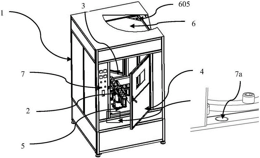
[0037] Centrifugal device of the present invention, such as figure 1 As shown, it is mainly composed of a frame 1 and an operation door 4; the structure in the frame 1 includes a rotor 2, a rotating chamber 3, a rotary drive mechanism 5, a hot air circulation part 6 and a control device 7; the frame 1 is provided with a fixed rotary drive The support position of the mechanism 5 and the support position of the fixed hot air circulation part 6; the operation door 4 is connected to the frame 1 by means of side hinges, and its position is set on two opposite sides of the frame 1 for covering the rotating Chamber 3, thereby forming a closed rotating space, and an observation window is provided on the operation door 4, which is convenient for observing the operation conditions in the rotating chamber 3.

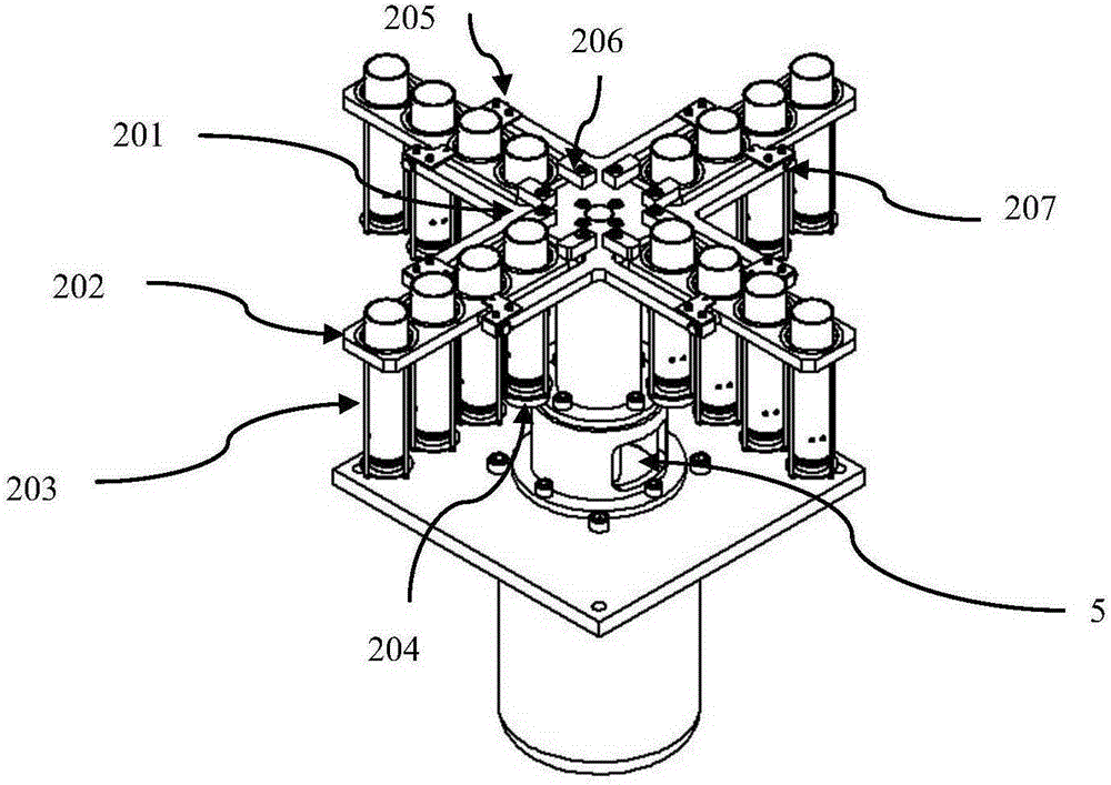
[0038] Wherein the rotor ...


PUM


Abstract

The invention discloses a centrifuging device comprising a rack, an operation door, a detection part, a hot air circulation part and a control device, wherein a rotor is a rotatable tool clamp provided with a containing product and is fixed on a rotation driving mechanism; a rotation chamber is arranged in the rack and can contain the three-dimensional space of a rotation disc; the rotation driving mechanism comprises a driving part fixed on a supporting frame arranged in the rotation chamber; the driving part is provided with a driving shaft part which can be driven and can be rotatable; the detection part is used for detecting whether the operation door is in a close state; the detection part comprises a first sensor and a second sensor and is fixed in an operation door frame on the rack; the hot air circulation part comprises a fan, a heating pipe, and an air duct arranged in the rack; the control device can be used for performing rotation frequency setting, running time setting, hot air circulation time and temperature setting, and whole machine starting, stopping and sudden stopping. The device is used for achieving glue filling of a single film shell, and a centrifuging function of multiple film assemblies and also is used for effectively controlling the glue filling amount and the centrifuging function time.

Description

technical field [0001] The invention belongs to the technical field of membrane separation, and in particular relates to a centrifugal device, which is used in the glue sealing process in the hollow fiber membrane module manufacturing process. Background technique [0002] Hollow fiber membrane separation technology is a high-tech developed in the middle of the 20th century. The principle of hollow fiber membrane separation has developed rapidly in the world in the past 20 to 30 years, and its application fields have been very extensive, mainly including the food industry. , beverage industry, dairy industry, biological fermentation, biomedicine, pharmaceutical chemical industry, biological preparations, traditional Chinese medicine preparations, clinical medicine, printing and dyeing wastewater, food industry wastewater treatment, resource recovery and environmental engineering, etc. The hollow fiber membrane is like a fiber-shaped, self-supporting membrane. The raw water f...

Claims


Application Information

Patent Timeline
IPC IPC(8): B04B1/00B04B15/02B04B7/00B04B7/08B04B9/00
Inventor 李全昌臧济文
Owner 浙江洁弗环保科技有限公司
Why Eureka
Try Eureka