
Method for reducing electrode vibration amplitude of tubular electrode during electrolytic machining

An electrode and amplitude technology, applied in the field of electrolytic machining of tube electrodes, can solve problems such as difficult control, uneven fluid stress, small diameter, etc., to increase the surface of the workpiece to be ground, improve the roughness and machining accuracy, and reduce the abrasive particle size. Effect

Inactive Publication Date: 2015-12-30
SHANDONG UNIV OF TECH
View PDF6 Cites 11 Cited by
  • Summary
  • Abstract
  • Description
  • Claims
  • Application Information

AI Technical Summary

Problems solved by technology

However, there are still some problems in the electrolytic machining of tube electrodes that limit its development and application. Improving the machining quality of electrolytic machining has always been an important issue that electrolytic machining researchers are committed to solving.
In the process of tube electrode electrolytic machining, the hollow tube electrode used is usually small in diameter and poor in stiffness, and its hollow structure further weakens its stiffness; in addition, the change of electrolyte flow rate in the machining gap and the electrolyte fluid The change of stress will lead to non-uniform fluid stress acting on the tube electrode surface, and the presence of electrolyte eddy current in the gap further deteriorates the fluid stress distribution on the tube electrode surface
Therefore, the hollow tube electrode with poor rigidity tends to vibrate irregularly under the fluid stress of the variable and non-uniformly distributed electrolyte, and its vibration amplitude is difficult to predict and even more difficult to control, which seriously affects the electrolytic machining. Stability and forming accuracy of processing

Method used


Image

  • Method for reducing electrode vibration amplitude of tubular electrode during electrolytic machining
  • Method for reducing electrode vibration amplitude of tubular electrode during electrolytic machining

Examples


Embodiment Construction

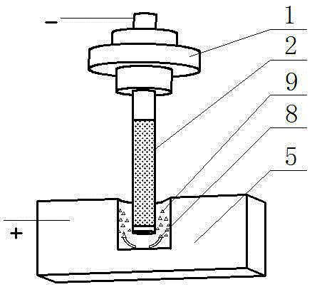
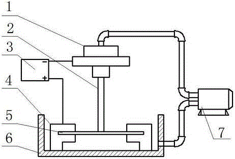
[0017] Such as figure 1 , 2 As shown, it includes: the clamping and sealing device 1 of the electrolytic processing machine tool, which is responsible for the clamping of the tube electrode and the sealing of the electrolyte; the tube electrode 2 is perforated and insulated on the side, and the upper end is connected to the clamping and sealing device 1 of the electrolytic processing machine tool , and connected to the negative electrode of the processing power supply as the cathode of the electrolytic processing, and spray the electrolyte downward during processing; the processing power supply 3 provides the required DC power during processing; the workpiece fixture 4 is responsible for clamping and fixing the workpiece; the workpiece 5 is connected to the positive electrode of the processing power supply 3 An anode for electrolytic machining; an electrolytic cell 6, which provides an electrolyte processing environment for electrolytic machining; an electrolyte circulation pu...


PUM


Abstract

The invention provides a method for reducing the electrode vibration amplitude of a tubular electrode during electrolytic machining. The method comprises the following steps: adding an aluminum oxide grinding material into electrolyte used in electrolytic machining, properly adding a dispersing agent, and forming electrolyte suspension liquid of the aluminum oxide grinding material; performing corresponding side surface insulation treatment on the tubular electrode used in electrolytic machining, wherein during machining, electrolyte downwards flows in the tubular electrode and is outwards sprayed from an outlet in the lower end of the tubular electrode. As the damp of the electrolyte added with the aluminum oxide grinding material is higher, the damp to the tubular electrode is increased during vibration, vibration caused by flowing of the electrolyte and insufficient rigidity of the tubular electrode is reduced, and the amplitude is reduced; meanwhile, the aluminum oxide grinding material in the electrolyte flows through an electrolytic machining region along with the electrolyte, and aluminum oxide grinding particles in the grinding material are in contact with the machined surface of a workpiece, so that a grinding effect is achieved, a flow marker on the machined surface of the workpiece is eliminated, and the coarseness on the machined surface of the workpiece and the machining precision are improved.

Description

technical field [0001] The invention belongs to the technical field of tube electrode electrolytic machining, in particular to a method for reducing the amplitude of tube electrode electrolytic machining electrodes. Background technique [0002] Tube electrode electrolytic machining is a process in which a hollow metal tube is used as the tool cathode to electrochemically etch the anode of the workpiece. It is often used in electrolytic drilling. The hole machining of aviation parts is one of its important application fields. With the advancement of modern aviation industry technology, the temperature before the turbine of the aero-engine continues to increase, and the hot-end parts of the engine (such as high-pressure turbine working blades, guide vanes, combustion chambers, etc.) have widely used film cooling technology, and each blade has dozens of There are up to tens of thousands of such film cooling holes in the combustion chamber. These parts are mostly made of high-...

Claims


Application Information

Patent Timeline
IPC IPC(8): B23H3/00B23H3/08
CPCB23H3/00B23H3/08
Inventor 李志永路文文臧传武王钦强崔庆伟聂云聪
Owner SHANDONG UNIV OF TECH
Learn More