Double-magnet double-rotor permanent magnet motor for flywheel

A technology of permanent magnet motor and double magnet steel, applied in the direction of electrical components, electromechanical devices, etc., can solve the problems of easy deformation of the stator, large size of the motor, and reduction of the magnetic density of the air gap

Inactive Publication Date: 2015-12-30
SHANGHAI XINYUE METER FACTORY
View PDF4 Cites 10 Cited by
  • Summary
  • Abstract
  • Description
  • Claims
  • Application Information

AI Technical Summary

Problems solved by technology

In order to achieve a large torque output, it is unrealistic to increase the output torque only by increasing the size of the motor or increasing the number of turns of the coil. This will lead to a large size of the motor, which will lead to a large size of the entire flywheel structure, and the structural layout It is unreasonable and the quality is heavy; since the stator frame is a thin-walled part, when the radial or axial size is large, the stator is easily deformed when the stator coil is wound and poured with external tooling epoxy resin, resulting in the stator and the The rotor interferes; in addition, if the diameter of the motor rotor is large, it is easy to interfere with the surrounding wheel body, and the structural design is difficult; if the air gap is increased, the structural interference problem can be avoided, but the magnetic density of the air gap will be reduced, thereby reducing the electromagnetic torque Output
[0004] Therefore, in the face of the high torque output requirements of the flywheel, the use of traditional DC brushless motors has limitations

Method used


Image

  • Double-magnet double-rotor permanent magnet motor for flywheel
  • Double-magnet double-rotor permanent magnet motor for flywheel

Examples


Embodiment Construction

[0016] Now, the present invention will be further explained by describing preferred specific embodiments according to the present invention in detail.

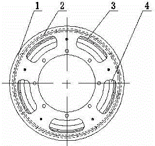
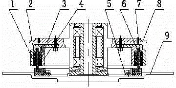
[0017] Such as figure 1 and figure 2 As shown, it is the dual-magnet double-rotor motor of this embodiment. The outer rotor 1 and the inner rotor 4 are made of pure electrical iron, which has good magnetic conductivity; the outer magnet 2 and the inner magnet 3 are both made of samarium cobalt permanent magnets. , with stable temperature characteristics and large remanence and coercive force. The magnetic steel adopts a tile-shaped structure, and the excitation direction is radial. The end surface of the outer rotor 1 is provided with a weight-reducing groove, and the inner side is provided with a positioning groove.

[0018] When assembling, the outer rotor 1 and the inner rotor 4 are connected with coaxial screws at first. Then the outer magnetic steel 2 is evenly distributed and fixed on the inner ring surface of the o...


PUM


Abstract

The invention relates to a double-magnet double-rotor permanent magnet motor for a flywheel. The double-magnet double-rotor permanent magnet motor includes a rotor assembly and a stator assembly; the rotor assembly comprises an outer rotor, outer magnets, an inner rotor and inner magnets; the rotor assembly is fixedly and coaxially connected with the bearing seat of the flywheel through the outer rotor; the outer rotor is coaxially and fixedly connected with the inner rotor; the outer magnets uniformly distributed on and fixedly connected with the inner ring surface of the outer rotor; the inner magnets are uniformly distributed on and are attached to the outer ring surface of the inner rotor; in the same radial dimension, the polarity of the outer magnets is opposite to the polarity of the inner magnets; the stator assembly includes a stator coil, a stator frame and a stator bracket; the stator assembly is connected with the supporting frame of the flywheel through the stator bracket; the stator coil is fixed on the stator bracket through the stator frame and is installed between the inner magnets and the outer magnets, so that two air gaps can be generated respectively. With the double-magnet double-rotor permanent magnet motor adopted, an air gap magnetic field can be improved, effective cutting axial length of the stator coil can be reduced, and copper loss can be reduced; and the axial length of the rotor assembly can be reduced, so that the axial length of the whole flywheel can be reduced, and the weight of an overall structure is small.

Description

technical field [0001] The invention relates to the field of spacecraft control, in particular to a double-magnetic-steel double-rotor permanent magnet motor for a flywheel, which is suitable for a satellite attitude control system. Background technique [0002] At present, most of the flywheel motors used in satellites are DC brushless motors, which have the characteristics of simple structure, linear mechanical characteristics, and wide speed range. In addition, a hollow cup stator is used, that is, the stator coil is wound on a non-metallic frame. Since there is no iron core, the cogging torque of the iron core profile is reduced. [0003] Accompanied by the large-angle maneuvering and side-swaying requirements of satellite attitude, the flywheel used by the satellite attitude control actuator is required to have a large output torque. In order to achieve a large torque output, it is unrealistic to increase the output torque only by increasing the size of the motor or...

Claims


Application Information

Patent Timeline
Patent Type & Authority Applications(China)
IPC IPC(8): H02K16/02
Inventor 王勇王超周华俊王森孙丹陶侃凯
Owner SHANGHAI XINYUE METER FACTORY
Why Eureka
Try Eureka