Method used for testing double-cladding gain fiber pump absorption coefficient

A gain fiber and absorption coefficient technology, applied in the direction of testing optical performance, etc., can solve the problem that the absorption coefficient of gain fiber cannot be given, and achieve the effect of eliminating unstable test results, improving accuracy and reducing transmission distance.

Active Publication Date: 2016-01-06
NAT UNIV OF DEFENSE TECH
View PDF4 Cites 7 Cited by
  • Summary
  • Abstract
  • Description
  • Claims
  • Application Information

AI Technical Summary

Problems solved by technology

For example, the absorption coefficient of ytterbium-doped fiber at 976nm is very large. When building a high-power fiber laser, the nonlinear e

Method used


Image

  • Method used for testing double-cladding gain fiber pump absorption coefficient
  • Method used for testing double-cladding gain fiber pump absorption coefficient
  • Method used for testing double-cladding gain fiber pump absorption coefficient

Examples


Embodiment 1

[0040] A method for testing the pumping absorption coefficient of double-clad gain fiber of the present invention comprises the following steps:

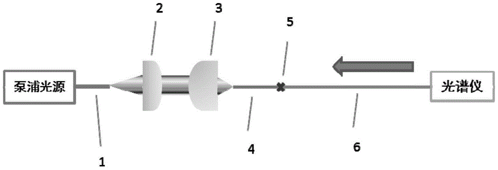
[0041] (1) Select the length L 0 A 1.57m double-clad gain fiber 6 to be tested. use as figure 1 In the test system shown, the double-clad gain fiber 6 to be tested is fused with the energy-transmitting fiber 4, and the parameters of the energy-transmitting fiber 4 (core diameter 30 μm, numerical aperture 0.07, inner cladding outer diameter 400 μm, numerical aperture 0.46) and The double-clad gain fiber 6 to be tested is consistent (the core diameter is 30 μm, the numerical aperture is 0.07, the outer diameter of the inner cladding is 400 μm, and the numerical aperture is 0.46), and the gain ion of the double-clad gain fiber 6 to be tested is Yb 3+ Ions, the gain absorption region is 850-1100nm. The full numerical aperture of the pump light is coupled into the inner cladding of the energy-transfer fiber 4 , and the power is monito...

Embodiment 2

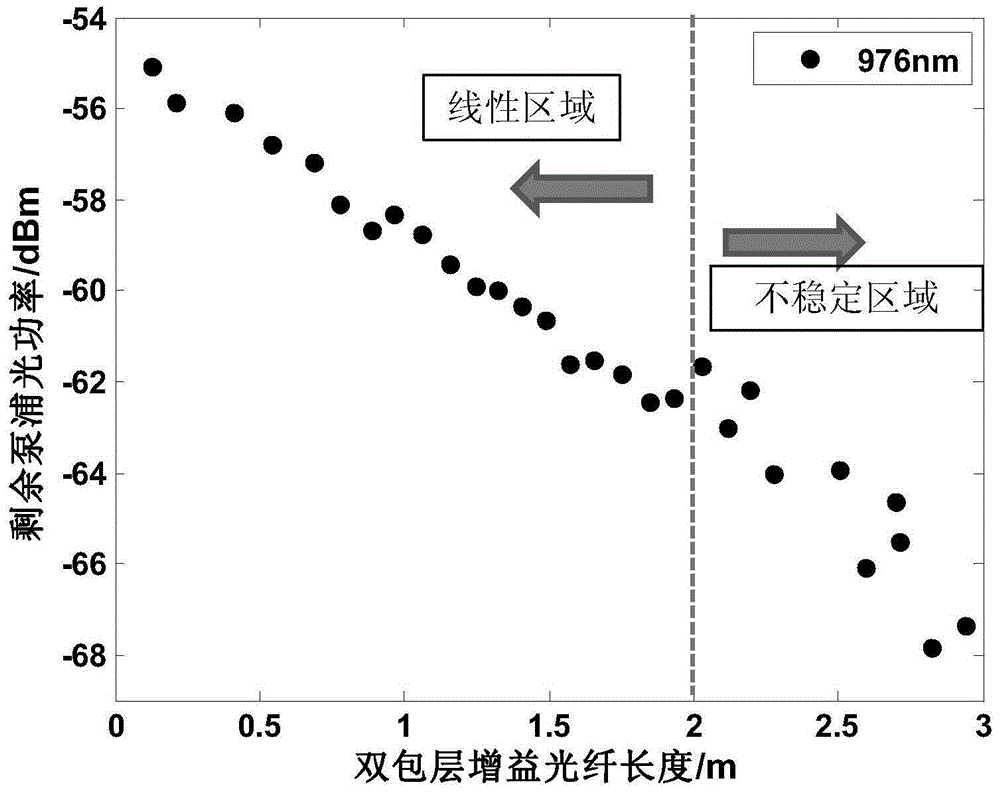
[0045] In order to study the influence of the length of the double-clad gain fiber 6 to be tested on the test results, the length L of the double-clad gain fiber 6 to be tested in the present embodiment 0 Choose 3m. After the optical path is built according to the test steps, the gain fiber is intercepted from the output end of the double-clad gain fiber to be tested to the direction of the energy-transmitting fiber. The length of the gain fiber is about 10 cm each time, and the output spectrum is tested after interception. Read the remaining pump light power of the 976nm band laser from the spectrum, such as image 3 shown. It can be seen from the figure that when the length of the double-clad gain fiber 6 to be tested is within 2m, the remaining pump light power decreases almost linearly with the increase of the gain fiber length; and when the fiber length is greater than 2m, the mode disturbance phenomenon Gradually affect the remaining pump light power, and the remaining...


PUM

PropertyMeasurementUnit
Lengthaaaaaaaaaa

Abstract

The present invention discloses a method used for testing a double-cladding gain fiber pump absorption coefficient. The method comprises the steps of (1) selecting a to-be-tested double-cladding gain fiber of which the initial length L0 is not more than 2m, welding the to-be-tested double-cladding gain fiber with a transmitting energy fiber, and coupling a pump light source into an inner cladding of the transmitting energy fiber; (2) cutting the to-be-tested double-cladding gain fiber, and testing the output powers of the pump light of different wavelengths in the pump light source under a test length L1; (3) repeating the step (2) to obtain the output powers of the pump light of different wavelengths when the length of the to-be-tested double-cladding gain fiber is L2, L3......LN separately; (4) finding out the residual pump light power of the light of which the wavelength is to be tested, and testing the pump absorption coefficient of the to-be-tested double-cladding gain fiber to the light of which the wavelength is to be tested. The method of the present invention can eliminate an unstable test result brought by the mode disturbance when the double-cladding gain fiber pump absorption coefficient is tested, and enables the accuracy and precision of the test result to be improved greatly.

Description

technical field [0001] The invention belongs to the field of fiber lasers, and relates to a method for testing the absorption characteristics of a gain fiber to pump light, in particular to a method for testing the pump absorption coefficient of a double-clad gain fiber. Background technique [0002] Compared with ordinary lasers, fiber lasers have obvious advantages in beam quality, volume, weight, efficiency, heat dissipation, etc., and have become one of the most popular research directions in the field of lasers. Single-clad gain fibers were often used in early fiber lasers, and both the pump light and the signal light were transmitted in the fiber core. Due to the small diameter and numerical aperture of the fiber core, the total power of the pump light injected into the gain fiber was limited. Restrictions restrict the power increase of fiber lasers. The structure of the double-clad gain fiber includes a core, an inner cladding and an outer cladding, and its character...

Claims


Application Information

Patent Timeline
IPC IPC(8): G01M11/02
Inventor 孔令超冷进勇郭少锋周朴许晓军姜宗福陈金宝
Owner NAT UNIV OF DEFENSE TECH
Why Eureka
Try Eureka