Optimization design method for optimum damping ratio of secondary transverse suspension of high-speed rail vehicle

An optimal damping ratio, high-speed rail technology, applied in computing, mechanical equipment, special data processing applications, etc., can solve problems such as the theoretical design method of the system that is not given, the difficulty of dynamic analysis and calculation, etc.

Inactive Publication Date: 2016-01-06
SHANDONG UNIV OF TECH
View PDF2 Cites 1 Cited by
  • Summary
  • Abstract
  • Description
  • Claims
  • Application Information

AI Technical Summary

Problems solved by technology

However, according to the available information, since the rail vehicle is a multi-degree-of-freedom vibration system, it is very difficult to perform dynamic analysis and calculation on it. At present, there is no system for the design of the damping ratio of the secondary lateral mount of the high-speed rail vehicle at home and abroad. Most of the theoretical design methods are to select a certain damping ratio based on experience (usually the empirical damping ratio is 0.2 to 0.4), and then, with the help of computer technology, use the multi-body dynamics simulation software SIMPACK or ADAMS/Rail to optimize throu...

Method used


Image

  • Optimization design method for optimum damping ratio of secondary transverse suspension of high-speed rail vehicle
  • Optimization design method for optimum damping ratio of secondary transverse suspension of high-speed rail vehicle
  • Optimization design method for optimum damping ratio of secondary transverse suspension of high-speed rail vehicle

Examples


Embodiment Construction

[0030] specific implementation plan

[0031] The present invention will be further described in detail through an embodiment below.

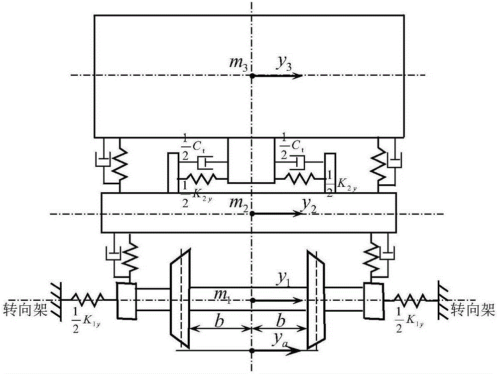
[0032] Two transverse shock absorbers are installed on each bogie of a high-speed rail vehicle, that is, n=2; the full-load mass of its 1 / 2 single-section car body m 3 =31983kg, the mass of a single bogie frame m 2 =2758kg, the equivalent mass of the wheel set m 1 =3442kg, each axle weight W=150000N; the equivalent stiffness K of the lateral positioning spring of a series of wheelset 1y =9784000N / m, the equivalent stiffness K of the central spring 2y =180000N / m; half of the lateral distance between the wheel and rail contact point b=0.7465m, the equivalent slope of the wheel tread λ=0.15, the lateral creep coefficient of the wheel f 1 =16990000N; the damping ratio of the secondary transverse mount to be designed is ξ, where the equivalent damping coefficient of the secondary transverse shock absorber The vehicle speed v=300km / h required fo...


PUM


Abstract

The present invention relates to an optimization design method for an optimum damping ratio of a secondary transverse suspension of a high-speed rail vehicle, and belongs to the technical field of high-speed rail vehicle suspensions. The method comprises: constructing a yawing vibration optimization design simulation model of a secondary transverse suspension system by establishing a 1/2 vehicle body driving yawing vibration differential equation and using MATLAB/Simulink simulation software; obtaining an optimum damping ratio, based on comfort and based on safety, of the secondary transverse suspension system by taking a non-smooth random input in an orbit direction as input excitation and taking a smallest vibration acceleration root mean square of the vehicle body and wheel yaw motion as a design target; and further carrying out calculation to obtain the optimum damping ratio of the secondary transverse suspension system. As known from design examples and SIMPACK simulation verification, an accurate and reliable optimum damping ratio of the secondary transverse suspension system can be obtained by the method provided by the present invention, thereby providing a reliable design method for the damping ratio of the secondary transverse suspension of the high-speed rail vehicle. By use of the optimization design method for the optimum damping ratio of the secondary transverse suspension of the high-speed rail vehicle, the design level of the suspension system of the rail vehicle and comfort and safety of vehicle riding can be improved.

Description

technical field [0001] The invention relates to a high-speed rail vehicle mount, in particular to an optimal design method for the optimum damping ratio of the secondary lateral mount of the high-speed rail vehicle. Background technique [0002] The damping ratio of the secondary lateral suspension system has an important influence on the ride comfort and safety of high-speed rail vehicles, and its design or selection is an important parameter for designing the shock absorber valve system parameters of the secondary lateral suspension system. However, according to the available information, since the rail vehicle is a multi-degree-of-freedom vibration system, it is very difficult to perform dynamic analysis and calculation on it. At present, there is no system for the design of the damping ratio of the secondary lateral mount of the high-speed rail vehicle at home and abroad. Most of the theoretical design methods are to select a certain damping ratio based on experience (us...

Claims


Application Information

Patent Timeline
IPC IPC(8): G06F17/50
CPCY02T10/40
Inventor 周长城于曰伟
Owner SHANDONG UNIV OF TECH
Why Eureka
Try Eureka