Mini broadband micro-strip array antenna

A microstrip array, broadband technology, applied in the field of array antennas in the field of wireless communication, can solve the problems of increasing the difficulty of broadband design and limited bandwidth expansion of the feeder network, achieving easy installation and integration, reducing the size of the antenna, and realizing broadband the effect of

Inactive Publication Date: 2016-01-06
CHINESE AERONAUTICAL RADIO ELECTRONICS RES INST
View PDF5 Cites 14 Cited by
  • Summary
  • Abstract
  • Description
  • Claims
  • Application Information

AI Technical Summary

Problems solved by technology

However, the bandwidth of these antenna structures is limited, and they are all unit structures, and the gain is generally only 6-9dB. In order to obtain greater gain or to achieve specific directional requirements, it is often necessary to use a microstrip antenna array composed of microstrip radiating elements. The influence of mutual coupling between radiating elements and the bandwidth limitation of the feed network will increase the difficulty of broadband design

Method used


Image

  • Mini broadband micro-strip array antenna
  • Mini broadband micro-strip array antenna
  • Mini broadband micro-strip array antenna

Examples


Embodiment Construction

[0023] Embodiments of the present invention will be described in detail below in conjunction with the accompanying drawings. This embodiment is carried out on the premise of the technical solution of the present invention, and the detailed implementation and specific operation process are given, but the protection scope of the present invention is not limited to the following implementation examples.

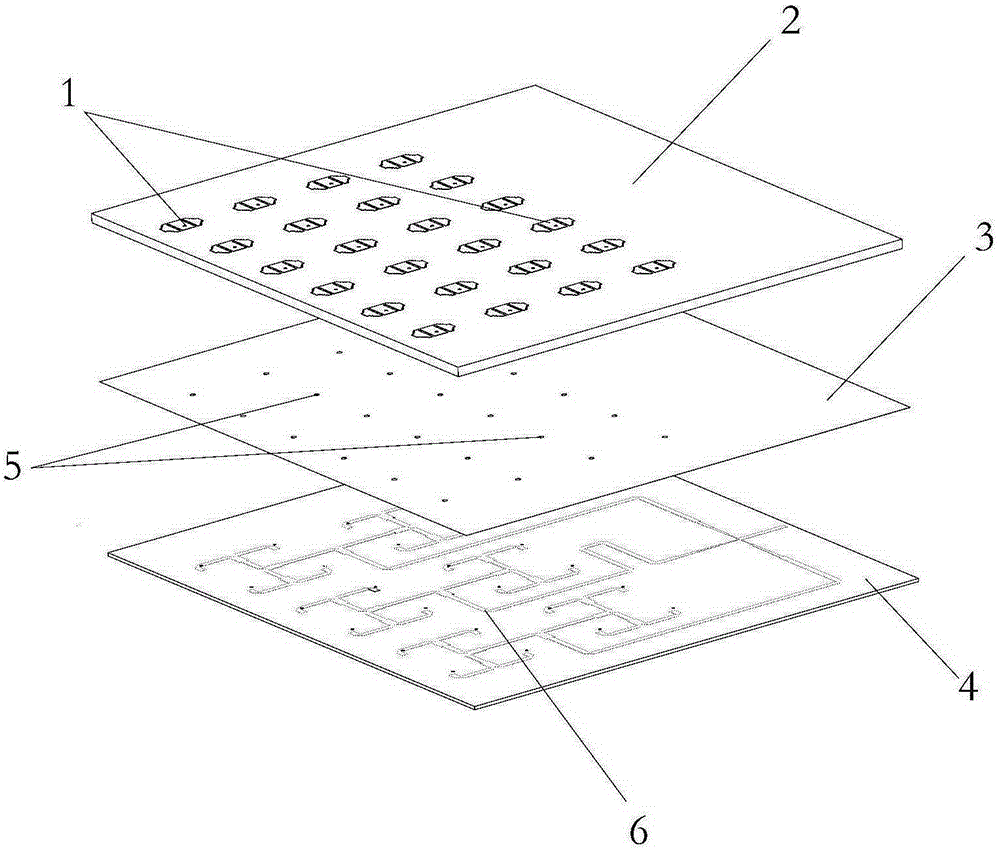
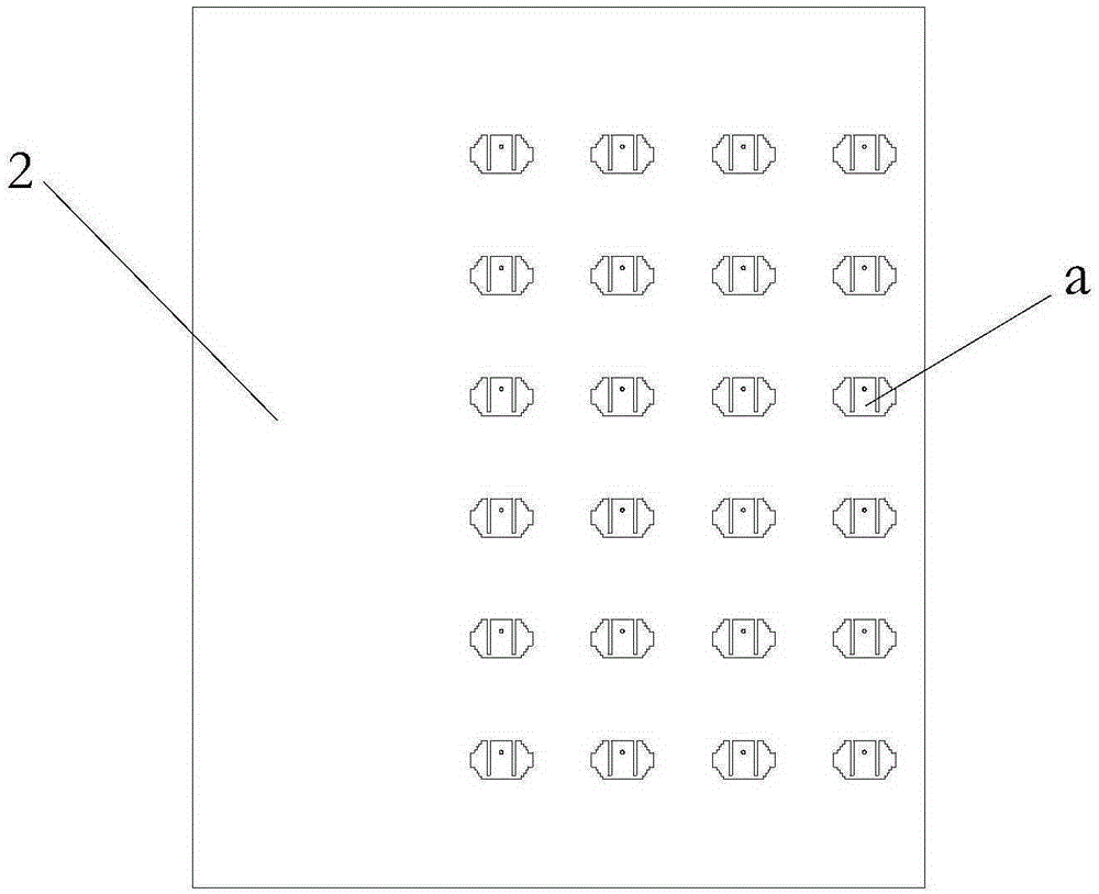
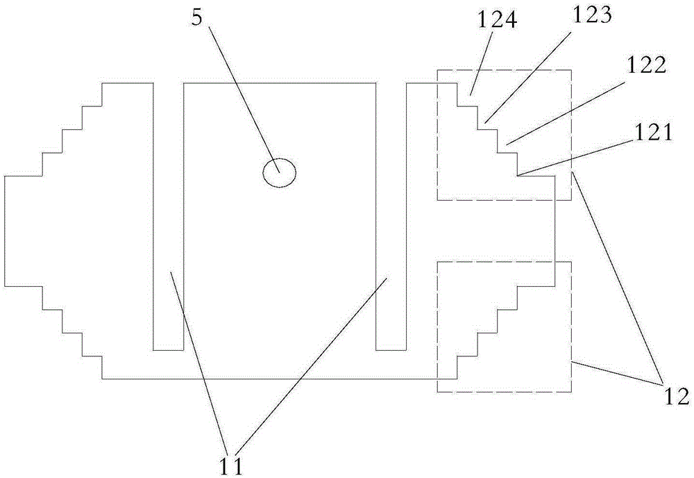
[0024] figure 1 A miniaturized broadband microstrip array antenna structure provided by the present invention is shown. The miniaturized broadband microstrip array antenna includes a radiation array 1, a first layer dielectric board 2, a metal floor 3, a second layer dielectric board 4, a probe 5 and a feed network 6, wherein the radiation array 1 is on the first layer On the upper surface of the dielectric board 2 , the feed network 6 is on the lower surface of the second dielectric board 4 . The metal floor 3 is located between the first dielectric board 2 and the second die...


PUM


Abstract

The invention relates to a mini broadband micro-strip array antenna. The antenna comprises a radiation array, the radiation array comprises multiple radiation paster units in an array structure of equal interval, in each radiation paster unit, rectangular grooves are formed in a rectangular paster in the axially symmetrical manner along the narrow side direction, and the top and bottom ends of the radiation paster unit include identical step-shaped gradually changed rectangular corner-cut structures respectively. Via the radiation array, the array antenna can only comprise the radiation array, a first dielectric plate, a metal ground plate, a second dielectric plate, pin and a feed network, wherein the radiation array is placed at the upper surface of the first dielectric plate, the feed network is placed at the lower surface of the second dielectric plate, the metal ground plate is placed between the first dielectric plate and the second dielectric plate, and the radiation array is connected with the feed network via punching by the pins. The current direction of the microstrip antenna is changed, multiple resonance frequency points can be added, and the broadband and mini design can be realized.

Description

technical field [0001] The invention relates to an array antenna in the field of wireless communication, in particular to a miniaturized broadband microstrip array antenna. technical background [0002] With the development of radio technology, the antenna is the front end of the radio frequency system, miniaturization and broadband work are the direction of its development. At present, microstrip antennas can easily realize the miniaturization of the structure, but the broadband work generally requires additional corresponding measures to achieve, such as multi-layer dielectric coupling patch, slot feed, etc. In order to improve the bandwidth of the microstrip antenna, researchers have developed many techniques to solve this problem. Sang-HyukWi et al. published a paper "WidebandmicrostrippattantennawithU-shapedparasiticelements" on IEEETransactionsonAntennasandPropagation in 2007. The paper presents a U-shaped parasitic patch microstrip antenna, using the gap between the ...

Claims


Application Information

Patent Timeline
Patent Type & Authority Applications(China)
IPC IPC(8): H01Q1/38H01Q1/50H01Q21/00
Inventor 徐飞张海辉丁勇飞叶俊杨俊鹏张雨农
Owner CHINESE AERONAUTICAL RADIO ELECTRONICS RES INST
Why Eureka
Try Eureka