A filter bag dust collector with self-circulation dust removal device
What is Al technical title?
Al technical title is built by PatSnap Al team. It summarizes the technical point description of the patent document.
A technology of dust cleaning device and dust collector, which is applied in the direction of dispersed particle filtration, chemical instruments and methods, and separation of dispersed particles. Large ground area and other problems, to achieve the effect of ensuring the blowing effect, reliable operation, and reducing the filtering wind speed
Active Publication Date: 2017-09-26
岳波
View PDF11 Cites 0 Cited by
Summary
Abstract
Description
Claims
Application Information
AI Technical Summary
This helps you quickly interpret patents by identifying the three key elements:
Problems solved by technology
Method used
Benefits of technology
Problems solved by technology
Filter bag service life is reduced, usually no more than 3 years
[0012] d. Due to the installation of the nozzle above the filter bag for the blown dust collector, it is extremely inconvenient to replace the filter bag and bag cage
[0013] e. The dust collector of line blowing adopts a circular filter bag to occupy a large area and the volume of the dust collector is large; although the dust collector of the rotary jet is a flat filter bag, it adopts an overall circular arrangement, and the volume of the four corners is wasted. The volume is also large;
[0014] f. The most critical thing is that the purge air source enters the dust collector, which increases the load of the induced draft fan of the boiler and increases the energy consumption
And produce fluctuating load (large when purging, small when not purging)
Method used
Image
Click on the blue label to locate the original text in one second.
Reading with bidirectional positioning of images and text.
Examples
Embodiment Construction
[0038] The present invention will be described in detail below in conjunction with the embodiments shown in the accompanying drawings.
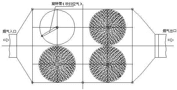
[0039] The self-circulation dust removal filter bag dust collector of the present invention includes a basic support, an air flow uniform distribution and flow guide device, a filter bag room, a clean air room, filter components (filter bags, bag cages, flower plates, etc.), and a self-circulation dust removal system. , ash hopper, electrical control system, insulation layer, platform, stairs, and a pre-painted ash system.
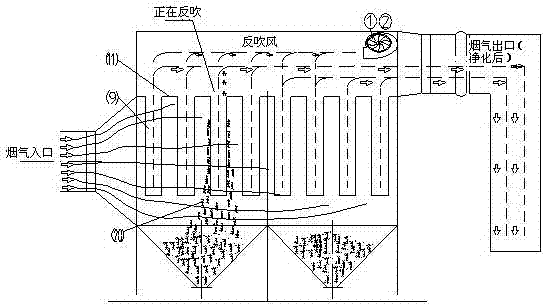
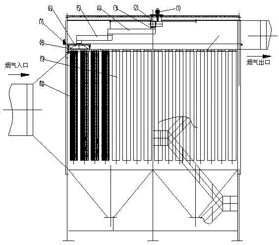
[0040] See image 3 , Schematic diagram of the working principle of the self-circulating dust-cleaning filter bag filter.
[0041] Among the figure: motor 1, centrifugal fan 2, filter bag 9, flower plate 11, dust 20.
[0042]The dust-laden flue gas from the boiler air preheater enters the bag filter through the flue at the flue gas inlet, and under the negative pressure of the induced draft fan, the flue gas enters the ...
PUM
Abstract
A filter bag type dust collector with a self-circulation dust removal device, relating to a dust collector, the dust collector includes a basic support, an air flow uniform distribution and flow guide device, a filter bag room, a clean air room, a filter assembly, a self-circulation Ash cleaning system, ash hopper, electrical control system, also includes insulation layer, platform, stairs, pre-coating system; the air inlet is equipped with airflow uniform distribution and flow guide devices, and the bag area is equipped with forward and upward airflow channels, The filter bags are arranged in groups in a rectangular room, and several filter bag openings are pressed together with a steel plate through bolts, so that the filter bags are firmly stuck in the hole of the flower plate. The filter bag holes are made on the flower plate, and the orifice plate is smooth without burrs. , The filter bag forms a double sealing structure on the upper part of the flower plate and the inner edge of the flower plate hole. The dust collector adopts the low-pressure air blowing generated by the centrifugal fan, and the airtight and non-leakage dust removal can not only ensure the blowing effect, but also prevent the filter bag from being slightly damaged, and the operation is safe and reliable. , to achieve the purpose of dust removal.
Description
technical field [0001] The invention relates to a dust collector, in particular to a filter bag type dust collector with a self-circulation dust removal device. Background technique [0002] Filter bag dust collector is the mainstream technology for flue gas dust removal in coal-fired power plant boilers. It is composed of ash hopper and electrical control system. [0003] The working principle of the filter bag dust collector is: the dusty flue gas from the boiler enters the filter bag dust collector through the flue of the flue gas inlet, and under the negative pressure of the boiler induced draft fan installed behind the dust collector, the dusty flue gas passes through and The air intake bell of the dust collector enters the bag filter, and passes through the air distribution plate of the filter bag filter to ensure the flow distribution of the flue gas before entering the filter bag bundle, avoiding the local dust-laden gas flow rate that is too fast to cause damage to...
Claims
Application Information
Patent Timeline
Application Date:The date an application was filed.
Publication Date:The date a patent or application was officially published.
First Publication Date:The earliest publication date of a patent with the same application number.
Issue Date:Publication date of the patent grant document.
PCT Entry Date:The Entry date of PCT National Phase.
Estimated Expiry Date:The statutory expiry date of a patent right according to the Patent Law, and it is the longest term of protection that the patent right can achieve without the termination of the patent right due to other reasons(Term extension factor has been taken into account ).
Invalid Date:Actual expiry date is based on effective date or publication date of legal transaction data of invalid patent.