Oil well acidification flowback liquid treating technology and device for offshore oil field

A technology for oil well acidification and offshore oilfields, which is used in oil/oil/float removal devices, mining wastewater treatment, heating water/sewage treatment, etc. Handling process interruptions, etc.

Active Publication Date: 2016-01-13
GREEN EARTH ENVIRONMENT TECH BEIJING CO LTD
View PDF8 Cites 4 Cited by
  • Summary
  • Abstract
  • Description
  • Claims
  • Application Information

AI Technical Summary

Problems solved by technology

During production, it was found that after participating in the process, it has a major impact on crude oil dehydration treatment and oily sewage treatment: First, for the treatment process without electric dehydrator, the acidified flowback liquid enters the production separator, causing impact load on the production process, The water content and mud content of the crude oil at the oil phase outlet increase; the oily sewage at the water phase outlet turns yellow, the oil content increases, and the mud content increases, and the treated sewage cannot meet the water quality indicators for water injection; The processing flow of the electric dehydrator thickens the emulsified layer of the liquid in the electric dehydrator and increases the current, which seriously affects the stable operation of the electric dehydrator.
Especially serious, power off the electric dehydrator
The consequence is that the electric dehydrator is powered off, and the production fluid treatment process is interrupted. In order to keep the treatment process uninterrupted, it is necessary to stop the acid fracturing operation measures; the stop of the acid fracturing operation measures will affect the crude oil production and economic benefits of the oilfield

Method used


Image

  • Oil well acidification flowback liquid treating technology and device for offshore oil field

Examples


Embodiment Construction

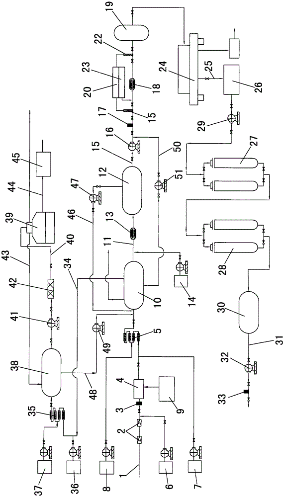
[0022] to combine figure 1As shown, the offshore oil well acidizing flowback liquid treatment device of the present invention includes a liquid inlet manifold 1, and two pressure reducing valves 2, a first flow meter 3, and a heat exchanger 4 are arranged on the liquid inlet manifold 1 from front to back And the first pipeline mixer 5, the part between the pressure reducing valve 2 and the first flow meter 3 on the inlet manifold 1 communicates with the corrosion inhibitor dosing device 6 through the pipeline, and the corrosion inhibitor dosing device 6 A corrosion inhibitor is placed in the inlet manifold 1, and the part between the heat exchanger 4 and the first pipeline mixer 5 on the inlet manifold 1 communicates with the demulsifier dosing device 7 and the reverse phase demulsifier dosing device 8 through the pipeline, Wherein, a demulsifier is placed in the demulsifier dosing device 7 , and a reverse phase demulsifier is placed in the reverse phase demulsifier dosing dev...


PUM

PropertyMeasurementUnit
densityaaaaaaaaaa

Abstract

The invention relates to an oil well acidification flowback liquid treating technology and device for an offshore oil field. The oil well acidification flowback liquid treating technology comprises the steps that acidification flowback liquid discharged out of a well opening of a Christmas tree is decompressed and heated up; a demulsifying agent and a reverse demulsifying agent are added, and the acidification flowback liquid is fed into an efficient separator for separation of oil, gas, water and mud; separated oily sewage is added with a water treatment agent and then fed into an oil and water separator, water discharged out of the oil and water separator is added with a PH value modifier, enters a pressure reactor to react and then enters a high-speed two-phase separating machine for separation of mud and water, separated water is subjected to fine filtering, oil discharged out of the efficient separator is added with a demulsifying agent and a desulphurizing reagent and then enters a free water removing device for removal of water, oil discharged out of an oil-phase outlet passes through an oil pump and a high-level intense demulsifying device and enters a high-speed three-phase separating machine for removal of water and mud, and the discharged oil enters an offshore oil production platform closed discharging system through excess pressure of the high-speed three-phase separating machine. According to the oil well acidification flowback liquid treating technology and device, the treatment efficiency is high, occupied space is small, transport and hoisting are convenient between offshore platforms, and with the combination of an efficient chemical agent, the acidification flowback liquid is quickly treated to reach the expected index.

Description

technical field [0001] The invention relates to the technical field of acidizing flowback liquid treatment technology and equipment, in particular to an acidizing flowback liquid treatment process and a processing device for oil wells in offshore oil fields. Background technique [0002] In offshore oilfields and onshore oilfields, the acidification of oil wells is one of the main measures to increase crude oil production and efficiency. In land oilfields, due to the limitation of the size of the site, a treatment pool is generally built next to the flowback well. After the flowback fluid is neutralized by adding alkali at the wellhead, it is discharged into the treatment pool. After natural settlement, the mud at the bottom is transported to the centralized sludge treatment station. The supernatant is sent to the sewage treatment station and mixed into the large process for unified treatment. Acidification flowback liquid production volume 10m 3 / h or so, large process ...

Claims


Application Information

Patent Timeline
Patent Type & Authority Applications(China)
IPC IPC(8): C02F9/10C02F1/02C02F1/40C02F103/10
Inventor 段明甄华锋李娟苗志超方申文
Owner GREEN EARTH ENVIRONMENT TECH BEIJING CO LTD
Why Eureka
Try Eureka