

Broadband dual circularly polarized antenna for detection of partial discharge of switchgear, and designing method thereof
A technology for detecting switches and partial discharges, applied in antennas, electrical components, radiating elements, etc., can solve the problems of fractal curve bending and distorting current direction, low polarization purity, and narrow detection frequency band, etc., to extend the effective electrical length , enhanced detection effect, moderately sized effect
- Summary
- Abstract
- Description
- Claims
- Application Information
AI Technical Summary
Problems solved by technology
Method used
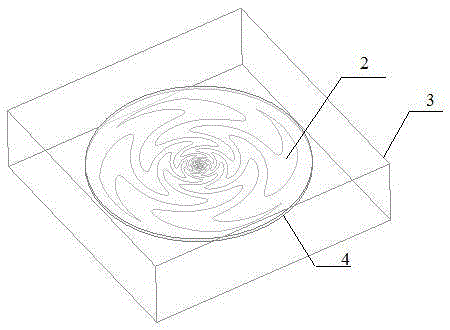
Image

Examples
Embodiment
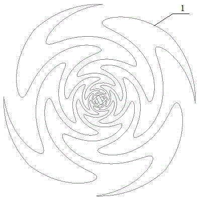
[0040] Embodiment: adopt the following steps to design a broadband dual circularly polarized antenna for detecting partial discharge in a switchgear
[0041] (1) Determine the antenna parameters: the number of conductor arms N, the return loss of the antenna Absolute value threshold and standing wave ratio threshold;
[0042] (2) Determining the contour line of the first conductor arm, which consists of the following specific steps:
[0043] Step 2-1: Set wire layer material, constant and angle span , the ratio of the radii of two adjacent curves , curve fine-tuning factor the initial parameters;
[0044]Step 2-2: Determine the initial shape of the outline of the first conductor arm, the basic sinusoidal curve of which is:
[0045] (2)
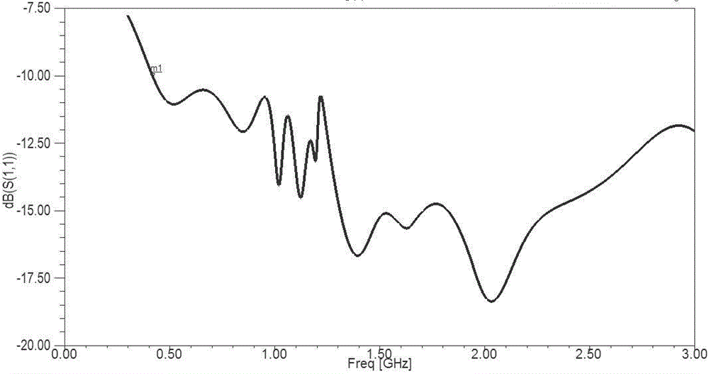
[0046] Step 2-3: Adjust Angle Span , the ratio of the radii of two adjacent curves , curve fine-tuning factor The value of , so that the return loss of the antenna The absolute value and standing wave ratio meet the thres...
PUM
| Property | Measurement | Unit |
|---|---|---|
| Thickness | aaaaa | aaaaa |
| Diameter | aaaaa | aaaaa |
Abstract
Description
Claims
Application Information