
Solar silicon wafer cutting method

A technology of solar silicon wafers and cutting methods, which is applied to working accessories, fine working devices, stone processing equipment, etc., can solve the problems of poor dispersion effect of mortar, reduced adsorption amount, and easy settlement, etc., to reduce the processing cost of silicon wafers , the fluctuation value is reduced, and the effect of reducing the amount of mortar

Inactive Publication Date: 2016-01-20
ZHEJIANG FORESTRY UNIVERSITY
View PDF5 Cites 6 Cited by
  • Summary
  • Abstract
  • Description
  • Claims
  • Application Information

AI Technical Summary

Problems solved by technology

The standard water content of cutting mortar is below 0.5%. The polyethylene glycol (PEG) in the cutting fluid is easy to absorb water during the cutting process, causing the water content of the mortar after cutting twice to rise to about 3%. SiC is dispersed in The hydrophilic PEG in the mortar is adsorbed on the surface of SiC through hydrogen bonds. After the water content of the mortar increases, because the hydrogen bonds of water molecules are more active than the hydrogen bonds of PEG, the adsorption amount of PEG on the SiC surface will be greatly reduced, resulting in being The SiC adsorbed by water is easy to settle, and the dispersion effect of the mortar becomes poor, which affects the yield rate of silicon wafers

Method used


Image

  • Solar silicon wafer cutting method

Examples


Embodiment 1

[0024] Embodiment 1, a kind of solar silicon chip cutting method of the present invention, comprises the following steps,

[0025] A. The cutting steel wire moves at high speed, so that the cutting mortar attached to the cutting steel wire acts on the lower surface of the silicon rod to be cut with a stable cutting force field, and the silicon rod moves from top to bottom to generate pressure on the cutting steel wire;

[0026] B. The cutting mortar dropped during the cutting process is recovered from the mortar tank under the cutting steel wire, and the stirring continues to be pumped to the nozzle, which continues to spray onto the cutting steel wire through the nozzle;

[0027] C. After the silicon rod is cut, the cutting mortar in the mortar tank is first introduced into the ultrasonic oscillator and then passed through the centrifuge to separate and recover silicon carbide and separation liquid;

[0028] D. Separate the separating liquid through a filter press; decoloriz...

Embodiment 2

[0059] Embodiment 2, a solar silicon wafer cutting method, the cutting mortar includes primary silicon carbide, recycled silicon carbide, primary cutting fluid and recycled cutting fluid, the mass ratio of primary silicon carbide and recycled silicon carbide is 4:6-0:10, By adding raw cutting fluid and recycled cutting fluid at a mass ratio of 1:1-3:7, the mortar density can reach 1.625-1.635kg·L -1 .

Embodiment 3

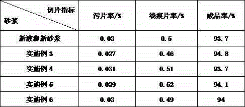
[0060] Embodiment 3, a solar silicon wafer cutting mortar, the mass ratio of primary silicon carbide and recycled silicon carbide used once is 1:9-0:10, and the mass ratio of adding primary cutting fluid to recycled cutting fluid is 1 :1-2:8, make the mortar density reach 1.625-1.635kg·L -1 .


PUM

PropertyMeasurementUnit
Power densityaaaaaaaaaa

Abstract

The invention provides a solar silicon wafer cutting method. The solar silicon wafer cutting method comprises the following steps that A, a cutting steel wire moves at a high speed, and a silicon rod moves from top to bottom to generate pressure on the cutting steel wire; B, cutting mortar falling in the cutting process is continuously sprayed to the cutting steel wire through a nozzle; C, after the silicon rod is cut, the cutting mortar in a mortar tank is guided into an ultrasonator, and then recycled silicon carbide and separating liquid are separated out by a centrifugal machine; and D, the separating liquid is separated through a filter press and is subjected to active carbon decoloration, filter aid filtration, resin exchange and dehydration by evaporation to obtain recycled cutting liquid. The solar silicon wafer cutting method has the beneficial effects that the mortar use amount in the silicon wafer machining process is effectively reduced by changing a silicon wafer cutting method, so that the silicon wafer machining cost is reduced, and the silicon wafer percent of pass is not reduced; waste mortar is recycled, so that the silicon wafer machining cost is reduced, and the fluctuating value of the silicon wafer percent of pass is reduced by 4.5%.

Description

technical field [0001] The invention relates to a solar silicon wafer cutting method which can not only effectively reduce the amount of mortar used in the silicon wafer processing process, but also greatly reduce the fluctuating value of the qualified rate of the silicon wafer. Background technique [0002] With the development of the photovoltaic industry in recent years, solar-grade polysilicon wafers have become upstream resources that major photovoltaic companies are vying for. The production cost of monocrystalline and polycrystalline silicon wafers has become the primary link affecting the photovoltaic industry. Therefore, the amount of cutting mortar necessary for the production of single crystal and polycrystalline silicon wafers has also increased rapidly. [0003] The cutting of solar silicon wafers for photovoltaics generally uses silicon carbide micropowder with high hardness, small particle size and concentrated particle size distribution as the main cutting me...

Claims


Application Information

Patent Timeline
IPC IPC(8): B28D5/04B28D7/00
Inventor 郇伟伟李洁李春锐周岩丁海军杨宇翔吕伟伟关莹郭建忠
Owner ZHEJIANG FORESTRY UNIVERSITY
Learn More