
Oil-gas mixing injection, lubricating and milling technology for high-intensity steel aerospace structure

A technology of aviation structural parts, oil and gas mixing, applied in milling machine equipment, milling machine equipment details, maintenance and safety accessories, etc., can solve the problems of unstable built-up edge, environmental pollution, difficult recovery and treatment of mineral oil, etc. effect, the effect of reducing the built-up edge

Inactive Publication Date: 2016-01-27
SICHUAN FUTURE AEROSPACE IND LLC
View PDF11 Cites 0 Cited by
  • Summary
  • Abstract
  • Description
  • Claims
  • Application Information

AI Technical Summary

Problems solved by technology

[0004] However, after the use of mineral oil, a large amount of mineral oil is extremely difficult to recycle and deal with, and waste mineral oil is a complex mixture of various substances, the main components of which are C15-C36 alkanes, polycyclic aromatic hydrocarbons (PAHS), olefins, Benzene series, phenols, etc., once entering the external environment, will cause serious environmental pollution;
[0005] Now a concept of dry cutting has been proposed in this technical field, but in practice, there are still many problems. It is basically a very unpopular field, and everyone is in the research and development stage;
[0006] In the field of aviation, such a problem is also involved. In this field, the utilization rate of high-strength steel is very high. Using traditional methods to process high-strength steel workpieces will also cause the above-mentioned pollution problem. Now in this dry cutting field , everyone is also trying, basically the most used is to set up a vortex tube, follow the movement of the tool, and spray cold air on the processing area, but in the actual use process, although the cooling effect is achieved, there will also be unstable products. The phenomenon of chipping occurs, and there are different dead angles in cooling and chip removal, resulting in extremely unstable processing, and the processing quality of high-strength steel workpieces in the aviation field cannot be guaranteed.

Method used


Image

  • Oil-gas mixing injection, lubricating and milling technology for high-intensity steel aerospace structure

Examples


Embodiment 1

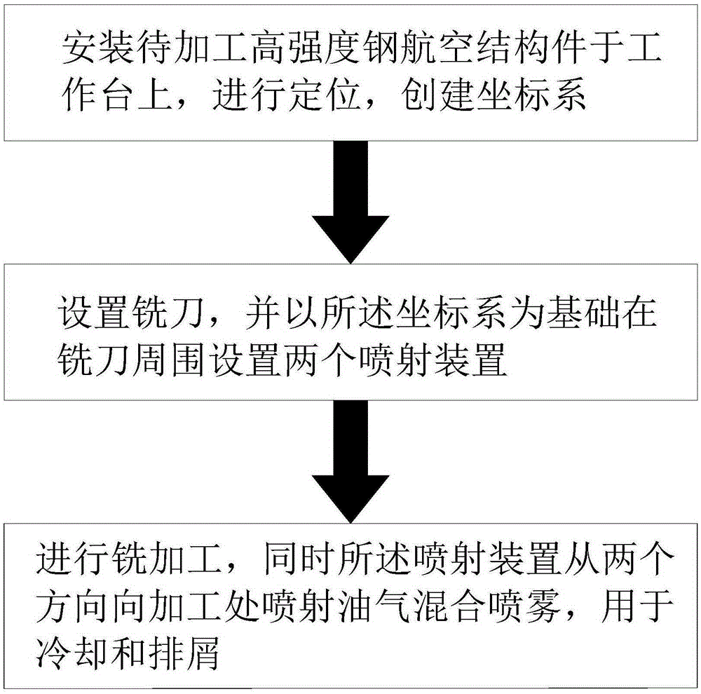
[0033] Such as figure 1 , a high-strength steel aerospace structural parts oil-air mixed jet lubrication milling technology, the steps are:

[0034] A. Install the high-strength steel aerospace structural parts to be processed on the workbench, perform positioning, and create a coordinate system;

[0035] B. The milling cutter is set, and two injection devices are arranged around the milling cutter based on the coordinate system, and the two injection devices are symmetrically distributed adjacent to each other;

[0036] C. Carry out milling, and at the same time, the injection device sprays oil-air mixed spray from two directions to the processing place for cooling and chip removal. The spray temperature is less than -5 °. In the oil-air mixed spray, the flow rate of oil is 10- 14ml / h.

[0037] In this embodiment, the injection device adopts a combination of a vortex tube and an oil dripping device, but the specific structure is not disclosed here. It is a brand-new struct...

Embodiment 2

[0042] In the present embodiment, except the technical scheme identical with embodiment 1, in step C, the flow rate of oil is 12-14ml / h.

[0043] In step B of this embodiment, when setting the milling cutter, it is different from the steps in embodiment 1. A rotating device (instead of the moving device) is provided on the spraying device to adjust the installation of a single spraying device. Angle, change the spray direction.

Embodiment 3

[0045] In the present embodiment, except the technical scheme identical with embodiment 1, in step C, the flow rate of oil is 10-12ml / h.


PUM


Abstract

The invention relates to the field of high-intensity steel aerospace structure machining, and in particular relates to an oil-gas mixing injection, lubricating and milling technology for a high-intensity steel aerospace structure. The technology comprises the following steps: A, mounting the high-intensity steel aerospace structure to be machined on a working table, positioning the structure, and establishing a coordinate system; B, arranging a milling cutter, and arranging two injection devices around the milling cutter on the basis of the coordinate system; and C, performing milling machining, and injecting oil-gas mixing spray to the machining part from two directions by the injection devices for cooling and slag discharging. The invention aims at providing the oil-gas mixing injection, lubricating and milling technology for the high-intensity steel aerospace structure, which can enhance the cooling effect and reduce the phenomenon of built-up edges.

Description

technical field [0001] The invention relates to the field of processing high-strength steel aerospace structural parts, in particular to an oil-gas mixed jet lubrication milling technology for high-strength steel aerospace structural parts. Background technique [0002] In the traditional cutting process, heat and cutting chips will be generated. If the heat exceeds a certain range, it will cause adverse effects. Excessive accumulation of cutting chips will also cause blockage and affect the processing of the workpiece; [0003] Therefore, in the prior art, during the cutting process, it will continuously or indirectly follow the tool, spray mineral oil to achieve cooling, and at the same time, flush the cutting fluid; [0004] However, after the use of mineral oil, a large amount of mineral oil is extremely difficult to recycle and deal with, and waste mineral oil is a complex mixture of various substances, the main components of which are C15-C36 alkanes, polycyclic aromat...

Claims


Application Information

Patent Timeline
IPC IPC(8): B23C3/00B23Q11/10B23Q11/00
CPCY02P70/10
Inventor 刘波姚佳志饶春红
Owner SICHUAN FUTURE AEROSPACE IND LLC
Learn More