
A method for measuring resistance, inductance and capacitance based on damped oscillatory waves in an oscillating circuit

A technology of damping oscillating waves and oscillating loops, which is applied in the field of sensor measurement, can solve the problems of affecting measurement accuracy, limiting measurement accuracy, detecting errors in voltage frequency and spectrum amplitude, etc., and achieves the effect of simple circuit structure and convenient use

Active Publication Date: 2017-12-01
ZHEJIANG UNIV
View PDF5 Cites 0 Cited by
  • Summary
  • Abstract
  • Description
  • Claims
  • Application Information

AI Technical Summary

Problems solved by technology

However, this measurement method has certain limitations: since this method directly calculates the sampled voltage information in the time domain, the sampled voltage itself is small and is easily affected by noise and parasitic parameters, which affects the measurement accuracy; in addition, the algorithm is effective The number of sampling points used is small, which is greatly affected by random errors, which limits the measurement accuracy
However, this frequency-domain algorithm based on standard discrete Fourier transform still has limitations: due to the limitation of sampling frequency and synchronous sampling, there must be cases of non-integer period sampling, that is, the detection voltage signal period is not an integer of the sampling period At this time, the standard discrete Fourier transform will have a truncation effect. The truncation effect includes spectrum leakage and inter-spectrum interference, resulting in errors in the calculated detection voltage frequency and spectrum amplitude, which limits the improvement of resistance (temperature) measurement accuracy.
[0005] The above two methods can be used for non-contact measurement of resistance, but the measurement accuracy is limited

Method used


Image

  • A method for measuring resistance, inductance and capacitance based on damped oscillatory waves in an oscillating circuit
  • A method for measuring resistance, inductance and capacitance based on damped oscillatory waves in an oscillating circuit
  • A method for measuring resistance, inductance and capacitance based on damped oscillatory waves in an oscillating circuit

Examples


Embodiment Construction

[0050] In order to describe the present invention more specifically, the measurement method of the present invention will be described in detail below in conjunction with the accompanying drawings and specific embodiments.

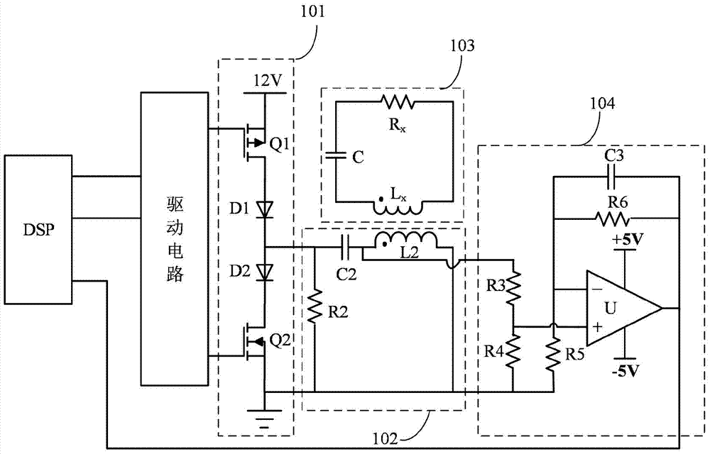
[0051] Such as figure 1 and figure 2 As shown, this embodiment provides a non-contact measuring device for resistance, inductance and capacitance, including: a controller, a drive circuit, a switch circuit 101 , a resonance circuit 102 , a signal detection circuit 104 and a series oscillation circuit 103 .

[0052] The driving circuit is connected to the controller, which amplifies the two driving signals provided by the controller and then outputs it; in this embodiment, the driving circuit adopts the IRF2110 chip of International Rectifier Company.

[0053] The switch circuit 101 is connected with the drive circuit, and outputs a square wave signal according to the two amplified drive signals provided by the drive circuit; in this embodiment, the switc...


PUM


Abstract

The invention provides a method for measuring resistance, inductance and capacitance based on damped oscillating waves in an oscillating circuit. The method adopts an improved discrete Fourier algorithm to realize high-precision measurement of resistance, inductance and capacitance parameters; wherein, The window function processing of the detection voltage signal can effectively suppress the influence of the truncation effect in the standard discrete Fourier transform, improve the accuracy of the Fourier transform, and then improve the measurement accuracy of the resistance, inductance and capacitance parameters. At the same time, on the basis of the detection voltage signal being processed by the window function, the measurement method of the present invention further adopts a single spectral line interpolation algorithm to correct the frequency calculation error caused by non-integer cycle sampling, and at the same time correct the frequency spectrum amplitude error caused by the truncation effect Corrections were made to further improve the accuracy of the measurement method.

Description

technical field [0001] The invention belongs to the technical field of sensor measurement, in particular to a method for measuring resistance, inductance and capacitance based on damped oscillation waves in an oscillation circuit. Background technique [0002] Resistors, inductors and capacitors are the three most basic electronic components. In the field of sensor measurement, many physical quantities can be transformed into measurements of resistance, inductance and capacitance. For example, the temperature can be measured by measuring the resistance of the thermistor; the distance between the coil and the metal object can be calculated by measuring the inductance of the coil; the distance between two metal plates can be obtained by measuring the capacitance. Typically, resistance, inductance, and capacitance can be accurately measured using bridge circuits. However, in some special occasions, such as the occasions where the resistance value is very small or the measured...

Claims


Application Information

Patent Timeline
Patent Type & Authority Patents(China)
IPC IPC(8): G01R27/02G01R27/26
Inventor 钱中南王睿驰王志鹍杜进吴建德何湘宁
Owner ZHEJIANG UNIV
Learn More