Artificial surface plasmon broadband bandstop filter based on composite U-shaped groove structure

A technology of artificial surface plasmon and band-stop filters, which is applied in waveguide devices, electrical components, circuits, etc., can solve the problems of complex filter structure, high processing difficulty, unfavorable mass production and processing, etc., and achieve light weight and structure New, simple, easy-to-integrate effects

Inactive Publication Date: 2016-01-27
CHINA UNIV OF MINING & TECH
View PDF6 Cites 11 Cited by
  • Summary
  • Abstract
  • Description
  • Claims
  • Application Information

AI Technical Summary

Problems solved by technology

However, the structure of the filter is relatively complicated. It is a resonant cavity with aperture coupling and then couple

Method used


Image

  • Artificial surface plasmon broadband bandstop filter based on composite U-shaped groove structure
  • Artificial surface plasmon broadband bandstop filter based on composite U-shaped groove structure
  • Artificial surface plasmon broadband bandstop filter based on composite U-shaped groove structure

Examples


Embodiment 1

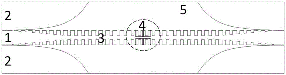
[0032] Embodiment 1: The filter includes a dielectric substrate 5 and metal printed on the dielectric substrate; the metal printed on the dielectric substrate includes: waveguide gradient structure 1, ground conductor plane 2, periodic metal grating waveguide 3 and U Type slotted structure 4; there is a U-shaped slotted structure on the periodic metal grating waveguide, and the U-shaped slotted structure means that no metal is printed;

[0033] The periodic metal grating waveguide is an artificial surface plasmon transmitter, and the two ends of the periodic metal grating waveguide are respectively connected to the waveguide gradient structure; the ground conductor plane is located on the upper and lower sides of the waveguide gradient structure;

[0034] The artificial surface plasmon transmitter is a metal film, and the shape of the metal film is that there are symmetrical grooves on both sides of the rectangle perpendicular to the length direction, and the grooves on the sam...

specific Embodiment

[0041] like figure 1 , the figure shows a schematic diagram of a U-shaped slot filter structure based on artificial surface plasmons, including a waveguide tapered structure, a ground conductor plane, a periodic metal grating waveguide, and a U-shaped slotted structure.

[0042] The periodic metal grating waveguide 3 is sequentially connected to the waveguide tapering structure and the ground conductor plane from the middle to both ends. The periodic metal grating waveguide 3 is an artificial surface plasmon transmitter. Metallic grating structures can be bent, folded, entwined, twisted, or wrapped on smooth or uneven surfaces to control conformal surface plasmon transport.

[0043] Among them, the artificial surface plasmon transmitters are composed of periodically arranged metal units, the shape of the metal units is rectangular, and the length and width of the metal units are the same. The metal unit is processed from metal thin film. The metal units are provided with gr...

Embodiment 2

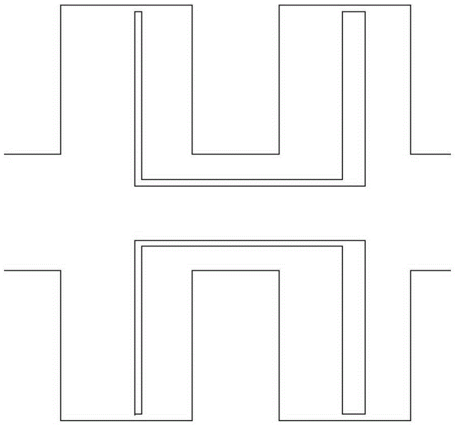
[0046] Embodiment 2: As shown in Figure 2(a), the figure is a partial view when the U-shaped slot structure 4 is two U's.

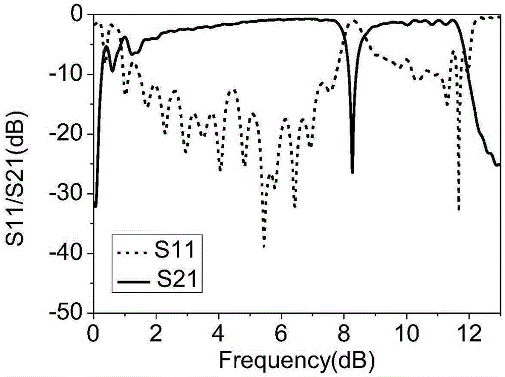
[0047]As shown in Figure 2(b), the filter performance curves of two U-shaped grooves include: S21 transmission coefficient and S11 reflection coefficient. The abscissa represents the frequency component, the unit is GHz, and the left ordinate represents the amplitude variable, the unit is dB. As can be seen from Fig. 2, the filter of two U-shaped grooves of the present invention, when frequency is 8.27GHz, transmission coefficient S21 is lower than-25dB, and the energy of output port is very little, and signal cut-off; And the transmission coefficient of other frequency S21 is about -1dB, the output port has a lot of energy and the signal passes through. Others are the same as in Example 1.


PUM

PropertyMeasurementUnit
Thicknessaaaaaaaaaa
Bandwidthaaaaaaaaaa

Abstract

The invention discloses an artificial surface plasmon broadband bandstop filter based on a composite U-shaped groove structure, and belongs to a bandstop filter. The filter comprises a dielectric substrate and metal printed on the dielectric substrate. The metal comprises a waveguide gradual change structure, grounding conductor planes, a periodic metal grating waveguide, and a U-shaped groove structure. The periodic metal grating waveguide is provided with the U-shaped groove structure, which indicates that no metal is printed. The periodic metal grating waveguide is an artificial surface plasmon transmitter, and two ends of the periodic metal grating waveguide are respectively connected with the waveguide gradual change structure. The grounding conductor planes are located at upper and lower sides of the waveguide gradual change structure. The artificial surface plasmon transmitter is a metal film, and the metal film is shaped in a manner that two sides, perpendicular to the length direction, of a rectangle are symmetrically provided with grooves. The grooves at the same side are arranged at equal intervals, and the widths and depths of the grooves are equal. The filter is simple in structure, is large in bandstop internal inhibition, is wide in band stop, and is easy to integrate with other microwave circuits.

Description

technical field [0001] The invention relates to a band-stop filter, in particular to an artificial surface plasmon broadband band-stop filter based on a composite U-shaped groove structure. Background technique [0002] A band-stop filter is a filter that passes most frequency components but attenuates certain ranges of frequency components to extremely low levels. Band-stop filters play an extremely important role in communication and signal processing systems. They are used to filter electromagnetic waves of unnecessary frequencies or suppress interference signals. They are indispensable functional devices in microwave and millimeter wave circuits and communication systems. [0003] In the 1960s, G.L. Matthaei made a systematic description of the design of the filter, and the description of the design of the band-stop filter is also more detailed, mainly Chebyshev and elliptic function, and its structure is composed of short truncated It is composed of line resonators, an...

Claims


Application Information

Patent Timeline
IPC IPC(8): H01P1/203
Inventor 李海鹏汪帅苏海李建东付文悦王昊深沈晓鹏韩奎
Owner CHINA UNIV OF MINING & TECH
Why Eureka
Try Eureka