Resin molding device and resin molding method
A resin mold and resin technology, applied in the fields of semiconductor/solid-state device manufacturing, electrical components, electrical solid-state devices, etc., can solve problems such as poor quality of molded products, and achieve the effects of improving quality, preventing poor appearance, and preventing leakage.
- Summary
- Abstract
- Description
- Claims
- Application Information
AI Technical Summary
Problems solved by technology
Method used
Image

Examples
no. 1 Embodiment approach
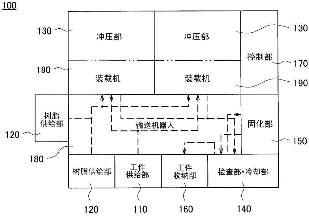
[0079] First, refer to figure 1 The resin molding apparatus 100 of this embodiment will be described. figure 1 It is a diagram showing the overall configuration of the resin molding apparatus 100 in a planar layout. Needless to say, the structure for performing resin molding, the resin molding apparatus 100 also includes a structure for heat-curing (post-curing) a good product after inspecting a resin-molded work (molded product) and storing it.
[0080] The resin molding apparatus 100 includes a workpiece supply unit 110, a resin supply unit 120, a press unit 130, a workpiece inspection unit / cooling unit 140, a curing unit 150 (curing furnace), and a workpiece storage unit 160 as a processing unit that performs various processing steps. . Furthermore, the resin molding apparatus 100 includes a control unit 170 for controlling each processing step. It is only necessary to configure each processing unit by at least one, but in the present embodiment, a case where the resin...
no. 2 Embodiment approach
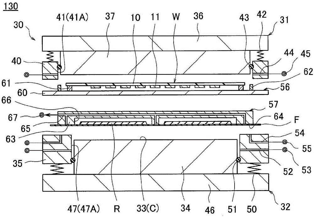
[0136] Compared with the first embodiment, in this embodiment, the workpiece loader 56 arranges (sets) the workpiece W together with the jig (the lower part of the upper die insert 37 ) on the upper die 31 , and the film loader 57 includes a heating There are differences in the parts, cooling parts, and gate parts. Below, refer to Figure 10 ~ Figure 14 The description will focus on this difference. Figure 10 ~ Figure 14 It is a schematic sectional view of the press part 130 of this embodiment.
[0137] As the workpiece W (substrate 10 ) becomes larger, the workpiece W is largely deflected (warped), so only the outer peripheral portion of the surface of the substrate 10 is used as in the first embodiment. 56 (support portion 61 ) holds the workpiece W, the substrate 10 bends due to its own weight and is difficult to hold in the mold, or falls during transportation. Therefore, in this embodiment, the plate-shaped jig 37A (member) is pushed against the back surface of the la...
no. 3 Embodiment approach
[0155] In the second embodiment, the film loader 57 uses the hand 63 that absorbs and holds the release film F on the side of the mounting surface on which the resin R is mounted, and supports the release film on the side opposite to the mounting surface. The case of the gate portion 70 of F is described. On the other hand, in the present embodiment, the film loader 57 is different in that the supporting resin R and the peeling film F are used and are arranged (set) as they are on the jig (member) of the lower mold 32 . Below, refer to Figure 15 ~ Figure 19 The description will focus on this difference. Figure 15 ~ Figure 19 It is a schematic sectional view of the press part 130 of this embodiment.
[0156] Like the second embodiment, in the shutter portion 70 supporting the release film F, it is necessary to wind up (remove) the shutter portion 70 when disposing the release film F on the lower mold 32 . At this time, there is a possibility that the distribution of the re...
PUM
| Property | Measurement | Unit |
|---|---|---|
| thickness | aaaaa | aaaaa |
Abstract
Description
Claims
Application Information
 - Generate Ideas
- Intellectual Property
- Life Sciences
- Materials
- Tech Scout
- Unparalleled Data Quality
- Higher Quality Content
- 60% Fewer Hallucinations
Browse by: Latest US Patents, China's latest patents, Technical Efficacy Thesaurus, Application Domain, Technology Topic, Popular Technical Reports.
© 2025 PatSnap. All rights reserved.Legal|Privacy policy|Modern Slavery Act Transparency Statement|Sitemap|About US| Contact US: help@patsnap.com