
Cast-welding method for lead-acid storage battery tabs

A lead-acid battery and battery technology, applied in the field of lead-acid battery pole lug casting and welding, can solve problems such as unenvironmental protection, lead liquid spillage, waste, etc., and achieve the effect of environmentally friendly solder and saving solder

Inactive Publication Date: 2016-02-03
厦门华海大正电池装备有限公司
View PDF10 Cites 11 Cited by
  • Summary
  • Abstract
  • Description
  • Claims
  • Application Information

AI Technical Summary

Problems solved by technology

[0003] 1. The volume of the lead furnace is large, and it takes a long time to heat the solid lead in it, and it also takes a long time to cool the lead liquid after heating. In the process of putting the casting mold into the lead liquid and taking it out, the lead liquid overflows and is wasted ;
[0004] 2. During the welding operation, the temperature of the molten lead liquid is high, and it is easy to volatilize harmful gases, which is not environmentally friendly
[0005] Chinese document CN200998765Y discloses a computer automatic casting and welding machine. The entire operation is controlled by a computer. Workers may cause lead poisoning during operation, which has certain hazards; , lead melting furnace, mold fixing seat, main cylinder, battery case fixture, electrical control box and heater with PLC, first auxiliary cylinder and second auxiliary cylinder, and also includes a drain valve, which is set behind the fuselage The side is connected with the lead melting furnace, and the electrical control box is set on the top of the fuselage through a rotating mechanism that can rotate 360°; when the machine is working, it is all closed, which reduces the harm of lead to the human body, but still needs to melt lead The furnace provides a large amount of molten lead, and does not solve the problem of accurate supply of lead

Method used


Image

  • Cast-welding method for lead-acid storage battery tabs

Examples


Embodiment

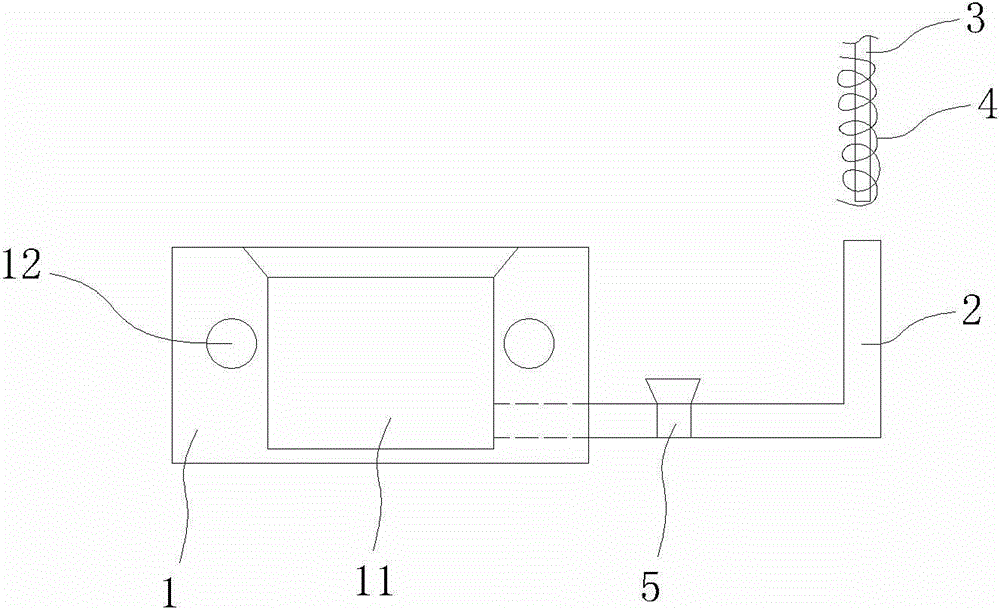
[0015] Example: see figure 1 , a lead-acid battery lug casting method, comprising the steps of: placing the battery pole plate on a casting mold 1, the mold is provided with at least one casting mold cavity 11, the side or bottom of the casting mold cavity passes through the connecting pipe 2 Inject a certain amount of molten lead liquid of V, the amount of lead liquid V is calculated in advance the amount of lead liquid required for welding the lugs of the cast welding mold, the entrance of the connecting pipe 2 is provided with a lead rod 3 and an induction heating device 4, and the induction heating The device quickly heats a section of lead rod 3 to form a lead liquid that drops into the connecting pipe and injects it into the cavity of the casting mold to achieve a certain amount of V, and then performs the lug casting operation. The casting mold cavity, the communicating pipe and the entrance of the communicating pipe of the casting and welding mold of the present invent...


PUM


Abstract

The invention discloses a cast-welding method for lead-acid storage battery tabs. The cast-welding method comprises the following steps that a storage battery pole plate is placed on a cast-welding mold which is at least provided with a mold cavity; a certain amount V of molten lead liquid is injected to the side face or the bottom of the mold cavity through a communicating tube, and the lead liquid amount V is the lead liquid amount needed for tab welding in the cast-welding mold; a lead rod and an induction heating device are arranged at an inlet of the communicating tube; the induction heating device quickly heats a section of lead rod to form lead liquid, and the lead liquid drops into the communicating tube and injected into the mold cavity; and then tab cast-welding operation is conducted. According to the cast-welding method for the lead-acid storage battery tabs, cast-welding lead liquid is supplied quantitatively through pipeline lead supplying, and the requirement for the lead liquid amount for cast-welding of a set of battery tabs in the mold is met; lead rod induction heating is used for lead liquid conveying, and quantitative material supply is achieved, so that the method has the advantages of power saving, environmental protection, welding material saving and the like.

Description

technical field [0001] The invention discloses a lead-acid accumulator lug casting welding method, which belongs to the technical field of lead-acid accumulator production technology according to the International Patent Classification (IPC). Background technique [0002] Lead-acid batteries are widely used in motorcycles, automobiles and other fields. Tabs are an important part of lead-acid batteries, and their quality directly affects the service life of batteries. Traditional tab welding processes use lead furnaces, furnaces Put solid lead in it and heat it to melt, put the casting mold into the lead liquid and take it out. The above welding method has the following defects: [0003] 1. The volume of the lead furnace is large, and it takes a long time to heat the solid lead in it, and it also takes a long time to cool the lead liquid after heating. In the process of putting the casting mold into the lead liquid and taking it out, the lead liquid overflows and is wasted ;...

Claims


Application Information

Patent Timeline
Patent Type & Authority Applications(China)
IPC IPC(8): B22D25/04B22D19/04
Inventor 张万生
Owner 厦门华海大正电池装备有限公司
Learn More