Automatic lifting plate shearing machine of back stop device and assembling and using method of automatic lifting plate shearing machine

A technology of automatic lifting and assembling method, applied in shearing devices, accessories of shearing machines, shearing machine equipment, etc., can solve the problems of large space occupation, low lifting safety and poor reliability of the back gauge device, and achieve easy Ingenious layout, structural design and responsive effect

Active Publication Date: 2016-02-03
ANHUI JACO NC MACHINE MFG
View PDF7 Cites 5 Cited by
  • Summary
  • Abstract
  • Description
  • Claims
  • Application Information

AI Technical Summary

Problems solved by technology

[0007] Aiming at the problems of low lifting safety, poor reliability and large space occupation of the back gauge device when the cutting length of the plate exceeds the positioning distance of the back gauge device of the existing plate shearing machine, the present invention provides a back gauge device that can automatically Lifting plate shearing machine and its ass

Method used


Image

  • Automatic lifting plate shearing machine of back stop device and assembling and using method of automatic lifting plate shearing machine
  • Automatic lifting plate shearing machine of back stop device and assembling and using method of automatic lifting plate shearing machine
  • Automatic lifting plate shearing machine of back stop device and assembling and using method of automatic lifting plate shearing machine

Examples


Embodiment 1

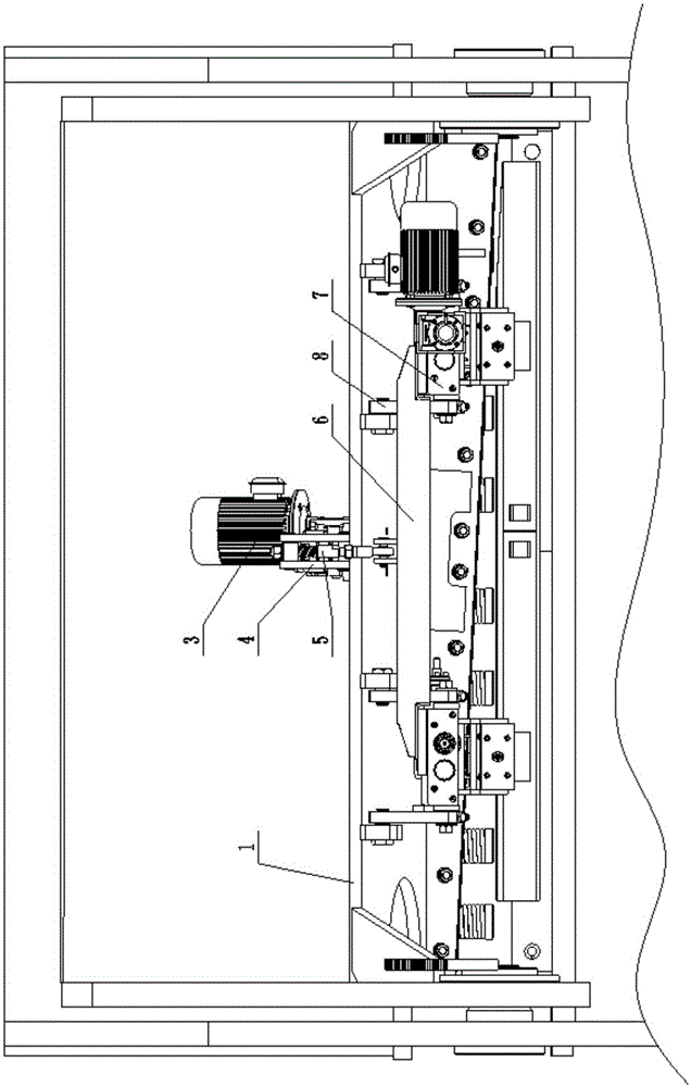
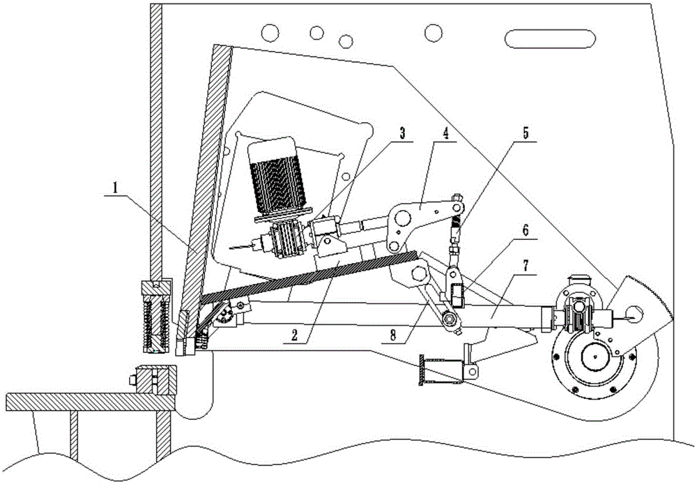
[0041] Such as figure 1 with figure 2 As shown, a shearing machine with a back gauge device in this embodiment that can be automatically raised and lowered includes a tool holder 1 , a back gauge device 7 , a pull rod device 5 , a connecting beam 6 and a material stop hanging plate 8 . Wherein, the rear side of the knife rest 1 is provided with an inclined support plate; one end of the support plate is connected to the lower part of the rear side of the knife rest 1, and a base 2 is arranged above the other end of the support plate. The base 2 is provided with a driving device 3 , and the front end of the base 2 is hinged with a rocker 4 .

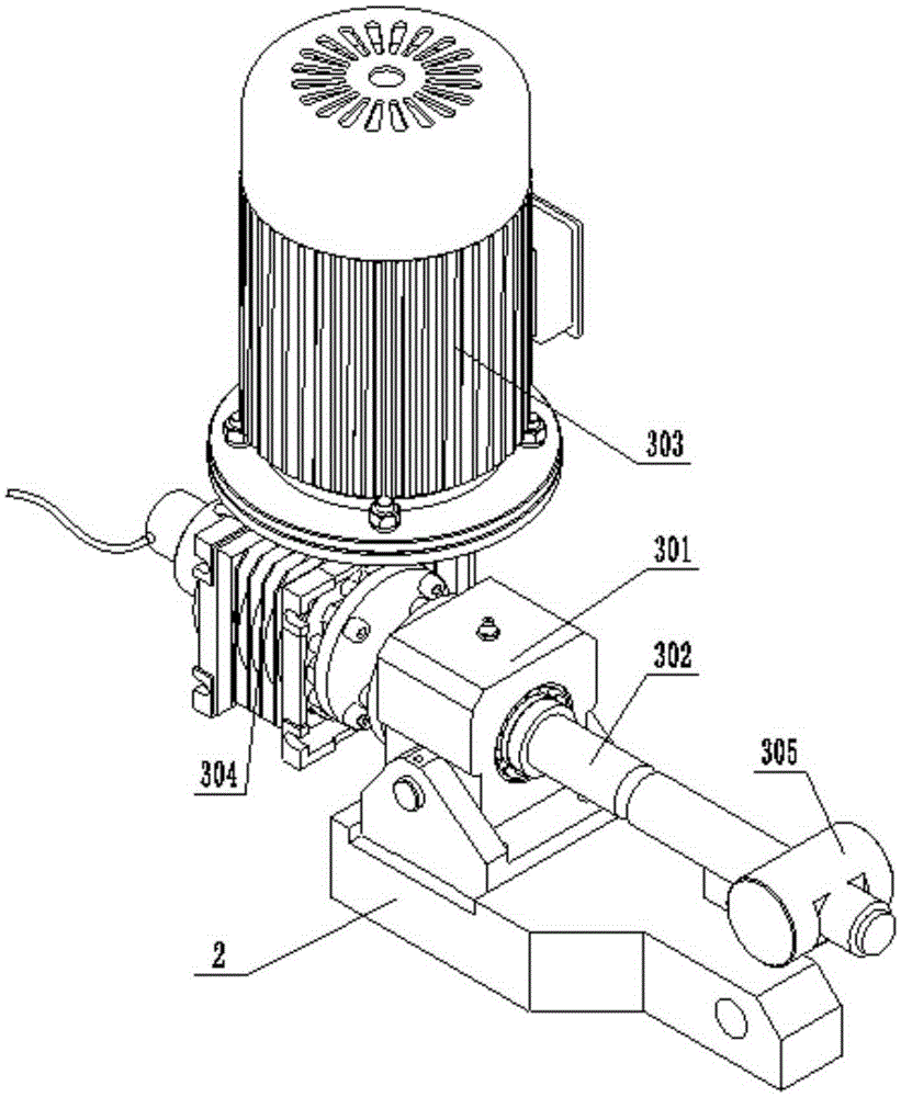
[0042] combine image 3 , the drive device 3 includes a bearing seat 301 hinged on the base 2, a drive shaft 302, a motor 303 and a reducer 304. The drive shaft 302 is connected to the bearing seat 301 through a bearing, and one end of the drive shaft 302 is threaded with a first pin shaft 305, the first pin shaft 305 is hinged with th...

Embodiment 2

[0055] In this embodiment, a shearing machine with a back gauge device that can be automatically raised and lowered has the same structure as that in Embodiment 1.

[0056] In this embodiment, record the linear distance from the hinge point of the first pin shaft 305 and the rocker arm member 4 to the hinge point of the rocker arm member 4 and the base 2 as L1, and the connection point between the pull rod device 5 and the rocker arm member 4 The linear distance between the arm 4 and the hinge point of the base 2 is L2, and L1:L2=1:3.

[0057] The above-mentioned method for assembling a shearing machine with a backgauge device that can be automatically raised and lowered, the steps are:

[0058] 1) Install the support plate to the knife rest 1, and install the knife rest 1 on the shearing machine;

[0059] 2) Firstly connect the front end of the back gauge device 7 to the support plate, and then connect the material hanger plate 8 to the support plate and the back gauge devic...

Embodiment 3

[0066] The structure and assembly method of a shearing machine with automatic lifting of the back gauge device in this embodiment are the same as those in Embodiment 1.

[0067] In this embodiment, record the linear distance from the hinge point of the first pin shaft 305 and the rocker arm member 4 to the hinge point of the rocker arm member 4 and the base 2 as L1, and the connection point between the pull rod device 5 and the rocker arm member 4 The linear distance between the hinge point of the arm 4 and the base 2 is L2, and L1:L2=1:2.7.

[0068] When using the above-mentioned shearing machine with automatic lifting of the rear gauge device, first turn the adjusting nut to adjust the pre-compression of the spring 504 to λ, λ=βF / k, where β is 0.9-1.2, F Be 1-1.4KN, k is the elastic coefficient of spring 504, in the present embodiment, get β=1.2, F=1.4KN, k=1.5*10 5 N / m, then λ=11.2cm; Then start the motor 303, and control the rotating speed of the drive shaft 302 to be 253...


PUM


Abstract

The invention discloses an automatic lifting plate shearing machine of a back stop device and an assembling and using method of the automatic lifting plate shearing machine, and belongs to the field of plate shearing machines. The plate shearing machine comprises a knife rest, the back stop device, a pull rod device and a connecting beam; an inclined supporting plate is arranged on the back side of the knife rest, and a base is arranged above the supporting plate; a driving device is arranged on the base, and a rocker arm piece is hinged to the front end of the base; the driving device comprises a driving shaft, and one end of the driving shaft is connected with the middle portion of the rocker arm piece; one end of the pull rod device is connected with one end, far away from the base, of the rocker arm piece, and the other end of the pull rod device is connected with the middle portion of the connecting beam; the two ends of the connecting beam are fixed to the back stop device; and the front end of the back stop device is hinged to the bottom of the supporting plate. By means of the automatic lifting plate shearing machine, automatic lifting of the back stop device can be achieved; and the automatic lifting plate shearing machine has the beneficial effects of being compact in structure, high in working efficiency, high in flexibility, high in accuracy, small in overall machine vibration and noise and long in service life.

Description

technical field [0001] The invention belongs to the field of shearing machinery, and more specifically relates to a shearing machine with a back gauge device that can be automatically raised and lowered, and an assembly and use method thereof. Background technique [0002] The shearing machine is a machine that uses one blade to make a reciprocating linear motion relative to the other blade to cut the plate. It uses the moving upper blade and the fixed lower blade, and adopts a reasonable blade gap to apply shear force to metal plates of various thicknesses, so that the plates are broken and separated according to the required size. The shearing machine is a kind of forging machinery, and its main function is the metal processing industry. The products are widely used in aviation, light industry, metallurgy, chemical industry, construction, shipbuilding, automobile, electric power, electrical appliances, decoration and other industries to provide the required special machin...

Claims


Application Information

Patent Timeline
IPC IPC(8): B23D15/06B23D33/00
CPCB23D15/06B23D33/00B23D33/10
Inventor 费文彪
Owner ANHUI JACO NC MACHINE MFG
Why Eureka
Try Eureka