
Method and equipment for recognizing bar codes of inner layers of circuit boards and printing codes on outer layers of circuit boards

A circuit board and barcode technology, applied in the field of circuit board identification, can solve problems such as scrapping, mixing circuit boards into other batches, and wrong operation by workers, and achieve the effect of simple equipment operation, improved production management level, and high degree of automation.

Inactive Publication Date: 2016-02-03
叶校然
View PDF5 Cites 5 Cited by
  • Summary
  • Abstract
  • Description
  • Claims
  • Application Information

AI Technical Summary

Problems solved by technology

Often there are several to hundreds of circuit boards in one lot card for one order. Because some products are very similar in appearance, circuit boards are often mixed into other batches. Because the processing parameters of different batches of circuit boards are different, once the order does not match Process parameters will cause scrap
[0005] Corresponding to the Lot card is the manual recording of production information in the workshop. You can only know which day and which process this batch of circuit boards were produced. In this way, if there is a quality problem with the product, it is impossible to find out which equipment is faulty. If any worker makes a wrong operation, when there is a problem with products involving the recall system, such as automotive panels, they can only be recalled in large quantities, and there is no way to make timely corrections to reduce losses, and there is no way to track and control them.
[0006] Printing a barcode on the edge of the circuit board can be used for production records and quality traceability, but for multi-layer circuit boards after the pressing process, the inner layer barcode is covered by resin and surface copper foil, if the inner layer barcode cannot be recognized, the inner layer and outer layer Layer-by-layer production records cannot be linked, and full-process quality traceability cannot be realized

Method used


Image

  • Method and equipment for recognizing bar codes of inner layers of circuit boards and printing codes on outer layers of circuit boards

Examples


Embodiment Construction

[0013] In order to describe in detail the structural features, technical means, and achieved goals and effects of the present invention, the following will be described in detail in conjunction with the embodiments and accompanying drawings.

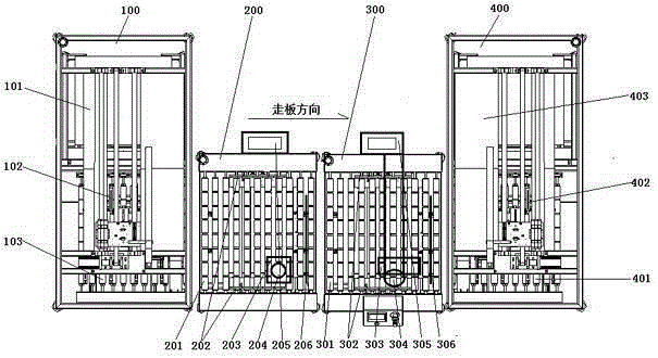
[0014] The equipment that recognizes the barcode on the inner layer of the circuit board and prints the code on the outer layer is mainly composed of a board feeding unit 100 , an X-ray inspection machine 200 , a laser coding host 300 and a board receiving unit 400 arranged in sequence.

[0015] The board feeding unit 100 includes a board placement platform 101 to be coded, a board feeding motion mechanism 102 and a board feeding roller group 103, and the board feeding motion mechanism 102 moves back and forth above the board placement platform 101 and the board feeding roller group 103.

[0016] The board receiving unit 400 includes a coded board placement platform 403, a board receiving motion mechanism 402 and a board receiving roller ...


PUM


Abstract

The invention provides a method and equipment for recognizing bar codes of inner layers of circuit boards and printing codes on outer layers of the circuit boards. The equipment is mainly composed of a board feeding unit, an X-ray checking machine, a laser code printing host and a board collecting unit. The method comprises the steps that the X-ray checking machine is used for obtaining images of the bar codes of the inner layers of the circuit board; image analysis software is used for recognizing the content of the bar codes, and the content is transmitted to a computer host of a laser code printing unit; and meanwhile the circuit boards move to the code printing host along rollers, and the corresponding bar codes are printed on the set positions of the outer layers of the circuit boards through a laser lens. The method and equipment are used for a circuit board quality tracking management system, the content of the bar codes of the inner layers of the circuit boards is recognized, and the corresponding bar codes are printed on the outer layers of the circuit boards. The equipment is easy to operate and high in automation degree, and the production and management level of circuit board enterprises can be remarkably improved.

Description

technical field [0001] The invention relates to a method and equipment for marking circuit boards, in particular to a method and equipment for identifying barcodes on the inner layer of the circuit board and printing codes on the outer layer. Background technique [0002] Laser marking is a marking method that uses a high-energy-density laser to locally irradiate the workpiece to vaporize the surface material or undergo a chemical reaction of color change, thereby leaving a permanent mark. Laser marking can print various characters, symbols, barcodes and patterns, etc., and the character size can range from millimeters to microns. [0003] Penetrating x-rays can penetrate substances that ordinary visible light cannot. The strength of its penetrating ability is related to the wavelength of x-rays and the density and thickness of the substance to be penetrated. It is commonly used in manufacturing to detect internal defects of metal components and identify internal image inf...

Claims


Application Information

Patent Timeline
IPC IPC(8): B41J2/435B41J3/407
Inventor 叶校然何立发
Owner 叶校然
Features
  • Generate Ideas
  • Intellectual Property
  • Life Sciences
  • Materials
  • Tech Scout
  • Unparalleled Data Quality
  • Higher Quality Content
  • 60% Fewer Hallucinations
Learn More