Optical imaging method

An imaging method and optical technology, applied in the direction of using optical devices, measuring devices, instruments, etc., can solve the problems of complex processing, high cost, difficult device manufacturing and processing, etc., and achieve simple information processing, simple manufacturing structure, and low cost. Effect

Inactive Publication Date: 2016-02-03
XIAN SIKUN ELECTRONICS SCI & TECH
View PDF0 Cites 5 Cited by
  • Summary
  • Abstract
  • Description
  • Claims
  • Application Information

AI Technical Summary

Problems solved by technology

At present, the following high-resolution optical three-dimensional imaging methods are used in the field of active machine vision and have their own problems: (1) The method of increasing the number of projected structured light fringes is adopted. When the number of projected fringes increases, the number of single projected fringes The narrower the width, it is limited by the imaging resolution of the imaging device itself and the front and rear occlusion of the unevenness of the object itself. When the number of stripes is too large or the width of a single structured light stripe is too narrow, it is very difficult for the computer to identify and the subsequent processing is complicated.
(2) The method of moving the optical three-dimensional imaging device or moving the measured object requires a large volume and high precision mechanical scanning device, resulting in a large volume, complex struct

Method used


Image

  • Optical imaging method
  • Optical imaging method
  • Optical imaging method

Examples


Embodiment Construction

[0020] In order to further illustrate the present invention, further describe below in conjunction with accompanying drawing and embodiment:

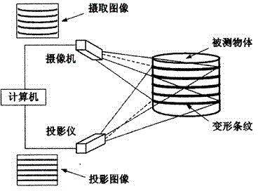
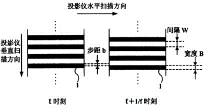
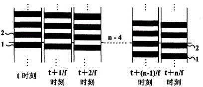
[0021] like figure 1 As shown, the computer controls the projector and the camera, and the projector emits a projection image and projects it onto the measured object, and the area array stripes in the projection image move in parallel according to the stepping frequency f. Deformation occurs when parallel area stripes are projected onto the object under test. The image of the deformed area array fringes is picked up by the camera, and collected to the computer through the image acquisition card. A common liquid crystal projector or the like may be used as the projector. The camera can adopt common CCD camera or CMOS camera etc. The effective field of view of the three-dimensional imaging is the intersection area of ​​the field of view of the projector and the camera. Within the effective field of view of 3D imaging, the projected s...


PUM


Abstract

The invention discloses an optical imaging method which is characterized in that resolution of a camera within an effective view field range of three-dimensional imaging and the dimension of structured light stripe width B, interval W and step b in a projected image after being subjected to projection and amplification within the effective view field range of three-dimensional imaging are calculated in advance by adopting a parallel translation area array stripe scanning mode; in the effective view field range of three-dimensional imaging, the dimension of the structured light stripe width B, interval W and step b generated by a projector and after being subjected to projection and amplification is equal to or larger than the minimum resolution of the camera in the direction of structured light stripe width; and high-resolution three-dimensional imaging of a detected object is realized through accumulated calculation. The optical imaging method realizes high-resolution three-dimensional imaging of the detected object, and can be used for designing and manufacturing high-resolution three-dimensional surface sensors which are simple in structure, small in size, simple in information processing and low in cost.

Description

technical field [0001] The invention relates to an optical imaging method. Background technique [0002] Optical three-dimensional imaging technology is an important part of machine vision research. As the "eye" of automation technology, it has extremely wide applications in many fields. The high-resolution optical three-dimensional imaging system can obtain more three-dimensional data on the surface of the measured object within the effective field of view composed of the projection light path of the projection device and the receiving light path of the camera, so as to achieve the goal of high sampling accuracy in three-dimensional space . At present, the following high-resolution optical three-dimensional imaging methods are used in the field of active machine vision and have their own problems: (1) The method of increasing the number of projected structured light fringes is adopted. When the number of projected fringes increases, the number of single projected fringes ...

Claims


Application Information

Patent Timeline
IPC IPC(8): G01B11/25
Inventor 袁博冯永强
Owner XIAN SIKUN ELECTRONICS SCI & TECH
Why Eureka
Try Eureka