
Driver of acousto-optic modulator
An acousto-optic modulator and drive device technology, which is applied to measuring devices, instruments, and measuring ultrasonic/sonic/infrasonic waves, etc., can solve the problem that the acousto-optic modulator cannot accurately obtain the orthogonal signal of the demodulation algorithm, and achieve simple structure, Improve the performance of system indicators
- Summary
- Abstract
- Description
- Claims
- Application Information
AI Technical Summary
Problems solved by technology
Method used
Image

Examples
Embodiment Construction
[0016] Referring to the accompanying drawings, the present invention will be further described in detail with specific embodiments.
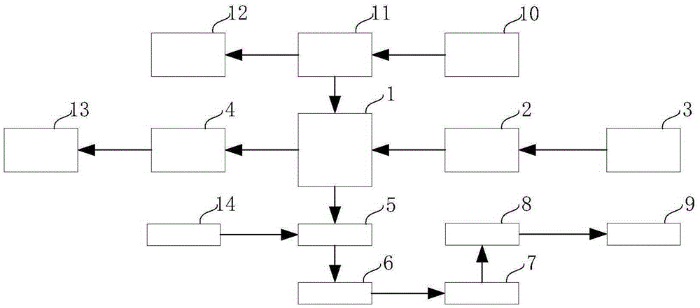
[0017] Such as figure 1 As shown, the acousto-optic modulator driving device includes a direct digital synthesizer 1, a controller 2, a communication interface 3, a current-to-voltage circuit 4, a pulse modulation circuit 5, a power amplifier circuit 6, an impedance matching circuit 7, a filter circuit 8, a radio frequency Output signal interface 9, crystal oscillator 10, clock distributor 11, synchronous clock output interface 12, quadrature analog signal output interface 13 and pulse trigger signal interface 14, the output end of controller 2 is connected to one input end of direct digital synthesizer 1 , the communication interface 3 is connected to the input end of the controller 2, one output end of the direct digital synthesizer 1 is connected to the input end of the current-to-voltage circuit 4, and the output end of the current-to-voltag...
PUM
 Abstract
Description
Claims
Application Information