Method and device for testing fluorescence life time

A fluorescence lifetime and measurement method technology, applied in fluorescence/phosphorescence, material excitation analysis, etc., can solve the problems of time-consuming adjustment and processing, complex optical path, expensive price, etc., achieve fast and high-throughput real-time online measurement, and simple device , low cost effect

Active Publication Date: 2016-02-03
ZHEJIANG UNIV
View PDF6 Cites 20 Cited by
  • Summary
  • Abstract
  • Description
  • Claims
  • Application Information

AI Technical Summary

Problems solved by technology

[0003] However, both of these technologies must use pulsed laser light as a light source, with a photomultiplier tube (or avalanche photodiode) and an enhanced charge-coupled device camera as a detector, which is very expensive
In addition, these two methods need to drive the detection device regularly according to the irradiation of the excitation light source, the optical path is complicated, and the adjustment and processing are time-consuming.

Method used


Image

  • Method and device for testing fluorescence life time
  • Method and device for testing fluorescence life time
  • Method and device for testing fluorescence life time

Examples


Embodiment 1

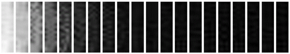
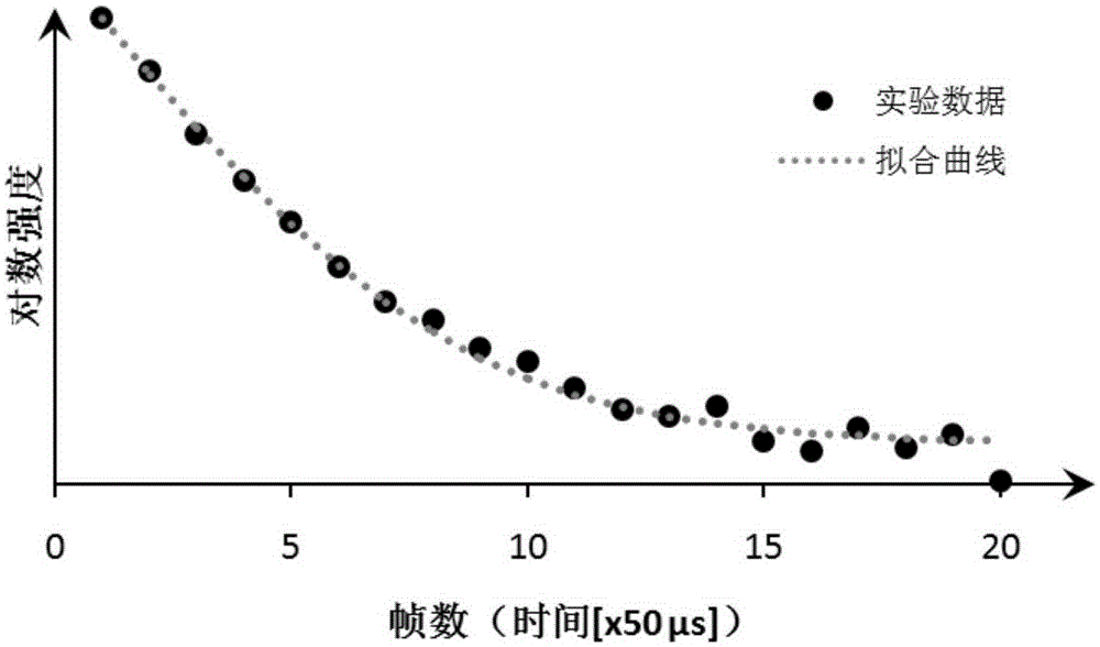
[0029] Fix the substrate with No. 1 fluorescent substance to be tested on the sample holder, and irradiate the sample with a pulse light source with a pulse repetition frequency of 1 kHz. The high-speed camera continuously shoots the fluorescent signal, and the exposure time of each frame is 50us. In the series of photos taken, a fluorescent signal corresponding to the repetition frequency of the excitation pulse appears, and the fluorescent signal changes periodically from strong to weak. A total of 20 photos in which the fluorescent signal continuously changes from strong to weak were randomly selected. Capture the corresponding position of the fluorescent substance in the photo, such as figure 1 shown. Then plot the sum of the gray values ​​of all pixels in each frame against time to obtain the fluorescence decay curve, as shown in figure 2 shown.

[0030] Then use the single exponential decay function I(t)=I bg +A·exp(-t / τ) fits the data points, where, I bg is the b...

Embodiment 2

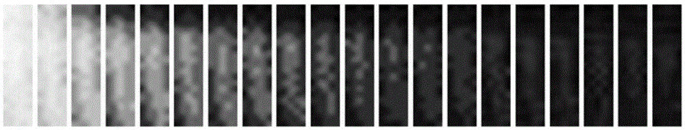
[0032] Fix the substrate with No. 2 fluorescent substance to be tested on the sample holder, and irradiate the sample with a pulse light source with a pulse repetition frequency of 1 kHz. The high-speed camera continuously shoots the fluorescent signal, and the exposure time of each frame is 50us. In the series of photos taken, a fluorescent signal corresponding to the repetition frequency of the excitation pulse appears, and the fluorescent signal changes periodically from strong to weak. A total of 20 photos in which the fluorescent signal continuously changes from strong to weak were randomly selected. Capture the corresponding position of the fluorescent substance in the photo, such as image 3 shown. Then plot the sum of the gray values ​​of all pixels in each frame against time to obtain the fluorescence decay curve, as shown in Figure 4 shown.

[0033] First use the single exponential decay function I(t)=I bg +A·exp(-t / τ) fits the data points, where, I bg is the ...

Embodiment 3

[0035] Fix the substrate with No. 3 fluorescent substance to be tested on the sample holder, irradiate the sample with a pulse light source, and operate according to the method of Example 1 (the exposure time of each frame is 100 μs, continuous shooting pulse light source excitation, repetition frequency is 500μs), get as Figure 5 Fluorescence decay images are shown. Due to the high pulse repetition frequency of the excitation light source, the fluorescence signal of the substance to be measured has not decayed to a lower value, and the next excitation pulse has arrived.

[0036] In this case, multi-segment fluorescence decay time series can be used for fitting, and the fitting result is as follows Figure 6 As shown, using the calculation formula in Example 2, the average value of the obtained fluorescence lifetime is 200 μs.


PUM


Abstract

The invention relates to a method and a device for testing fluorescence life time by utilizing simple configuration. The device comprises a sample carrying unit, an excitation unit, an imaging unit and a data processing unit, wherein a fluorescent sample is placed on the sample unit; the light source of the excitation unit is used for exciting the fluorescence of the sample; then the light source is turned off, and the fluorescence emitted by the sample is imaged in real time by using a measuring unit and the imaging unit, so as to obtain series of images showing that fluorescence intensity changes with time; the fluorescence life time can be calculated by utilizing the series of images. Compared with other methods and devices, the method and the device provided by the invention have the advantages that the device is simple, the cost is low, the operation is easy, and fast and high-flux real-time on-line measurement can be realized.

Description

technical field [0001] The invention relates to a fluorescence lifetime measurement method and device, which are used to detect the technical field of lifetime measurement and imaging of emitted light caused by excitation light irradiation. Background technique [0002] At present, there are two main methods for the measurement and imaging of fluorescence lifetime: one is to use time-correlated single photon counting (TCSPC) technology to measure the fluorescence lifetime, which uses photomultiplier tube or avalanche photodiode as scanning method for fluorescence lifetime imaging. The second is to use time-gated technology, using an enhanced charge-coupled device (ICCD) camera as a detector, and collect fluorescence signals with a delay of a certain time after each light pulse is excited, and repeat this process many times with different time delays. The fluorescence lifetime is measured, and then combined with the wide-field imaging method, the fluorescence lifetime imagin...

Claims


Application Information

Patent Timeline
Patent Type & Authority Applications(China)
IPC IPC(8): G01N21/64
CPCG01N21/64
Inventor 秦海燕彭笑刚
Owner ZHEJIANG UNIV
Why Eureka
Try Eureka