
A semiconductor laser cooling heat sink device

A technology of lasers and semiconductors, applied in the direction of semiconductor lasers, lasers, laser components, etc., can solve problems such as heat sink blockage, surface gold layer is easy to fall off, etc., to improve heat dissipation capacity, improve heat exchange efficiency, and avoid thermal stress and thermal stress. The effect of resistance

Inactive Publication Date: 2018-10-30
BEIJING UNIV OF TECH
View PDF9 Cites 0 Cited by
  • Summary
  • Abstract
  • Description
  • Claims
  • Application Information

AI Technical Summary

Problems solved by technology

And the performance of the oxygen-free copper material needs to be plated with gold. After long-term use, the gold layer on the surface is easy to fall off and cause the heat sink to be blocked.

Method used


Image

  • A semiconductor laser cooling heat sink device
  • A semiconductor laser cooling heat sink device
  • A semiconductor laser cooling heat sink device

Examples


Embodiment 1

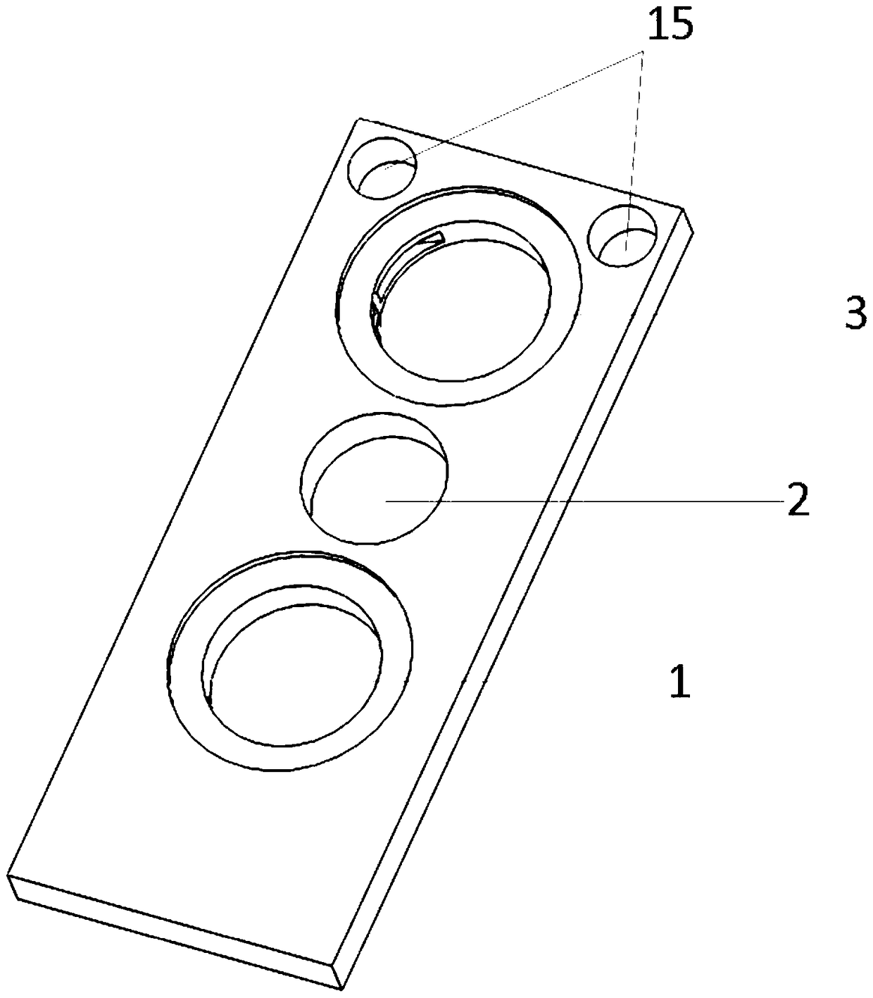
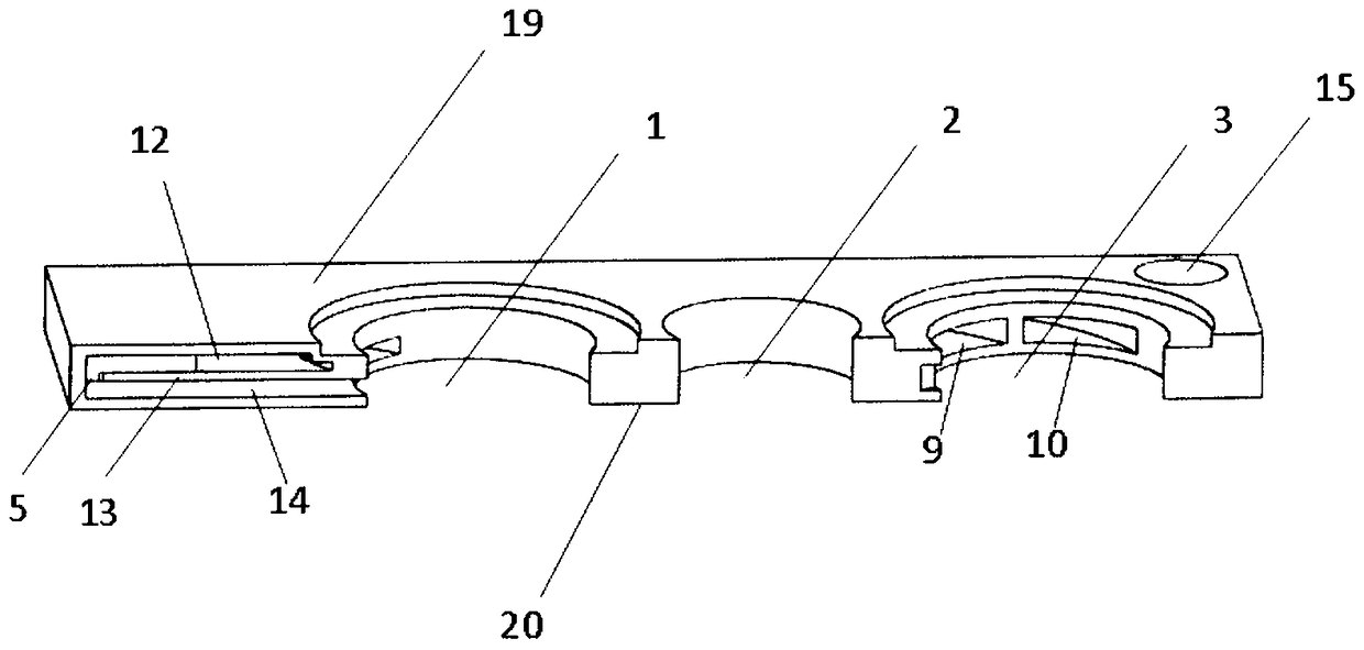
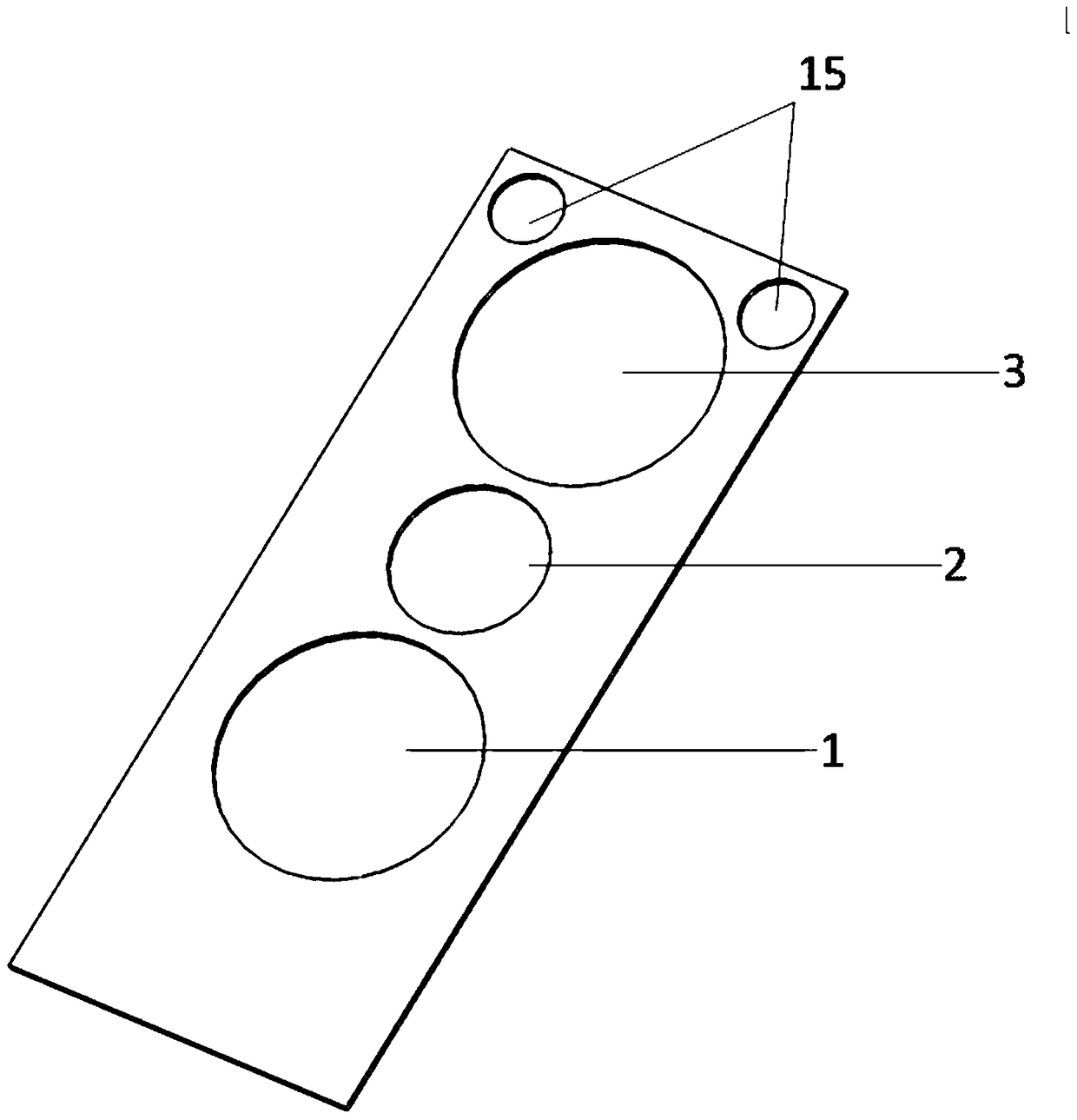
[0047] This embodiment provides a semiconductor laser cooling heat sink device. Among them, such as figure 1 , 2 As shown, the device also includes positioning holes 2 and screw holes 15 . The positioning hole 2 is arranged between the water inlet hole 1 and the water outlet hole 2 . The water inlet hole 1 , the positioning hole 2 and the water outlet hole 3 are all connected to the water inlet side cover 19 , the water inlet layer 12 , the guide layer 13 , the water return layer 14 and the water return side cover 20 . The screw holes 15 are preferably arranged on two corners on one side of the water outlet hole of the device, and are also connected to the water inlet side cover 19, the water inlet layer 12, the guide layer 13, the return water layer 14 and the return water side cover 20. Both the positioning holes 2 and the screw holes 15 are used to fix the entire heat sink device. Such as Figure 4 , Figure 5 As shown, the structure of the water inlet side cover 19 a...

Embodiment 2

[0054] This embodiment provides a semiconductor laser cooling heat sink device. The heat sink device is integrally formed. Wherein preferably, based on 3D printing, it is integrally formed in the vertical direction from one end of the device provided with the laser rake to the other end. And in order to facilitate integral molding, such as Figure 5 As shown, the angle between the hypotenuse of the slow flow area 4 at the opening of the water inlet hole 1 in the water inlet layer and the edge of the device near the laser rake is preferably greater than 45 degrees. Other features of the heat sink device provided in this embodiment are the same as those in Embodiment 1, and will not be repeated here.

[0055] The 3D printing integrated cooling heat sink device provided in this embodiment avoids the additional thermal stress and thermal resistance caused by the welding of various layers in the prior art. In addition, the material of the device is nickel-based alloy powder or t...


PUM


Abstract

The invention relates to the technical field of semiconductor laser arrays, and discloses a semiconductor laser cooling heat sink device. The semiconductor laser cooling heat sink device comprises a water inlet side cover, a water inlet layer, a guide layer, a water return layer and a water return side cover, which are sequentially arranged, wherein a water inlet hole is formed in the outer surface of the water inlet side cover; a water outlet hole is formed in the outer surface of the water return side cover; a slow flow region for slowing down the flow rate of a heat-conducting medium is formed among the water inlet side cover, the water inlet layer and the guide layer; a plurality of through holes through which the heat-conducting medium flows into the water return layer from the slow flow region are formed in one side, close to a semiconductor laser in the guide layer; and a water outlet channel through which the heat-conducting medium flows outside is also formed among the guide layer, the water return layer and the water return side cover. The semiconductor laser cooling heat sink device provided by the invention is a 3D printing integrated forming device; thermal stress and thermal resistance caused by welding of various layers in the prior art are avoided; heat-sink blocking due to the fact that a gold-plated material on the inner wall of the device falls off is also avoided; and the heat exchange efficiency is improved.

Description

technical field [0001] The invention relates to the technical field of semiconductor laser arrays, in particular to a semiconductor laser cooling heat sink device. Background technique [0002] Semiconductor lasers have the characteristics of high electro-optical conversion efficiency, small size, light weight, and long life, which make them widely used. Improving output power and beam quality has always been the main research topic of high-power semiconductor lasers. As the power of semiconductor lasers continues to increase, the power density continues to increase, and the high heat of the laser chip directly affects the life of the semiconductor laser. In view of the above problems, a microchannel cooling heat sink is generally used to reduce the heat of the laser chip. [0003] The monolithic microchannel cooling heat sink in the prior art is composed of five layers of oxygen-free copper sheets with different shapes, and the laser chip is located on the upper surface of...

Claims


Application Information

Patent Timeline
Patent Type & Authority Patents(China)
IPC IPC(8): H01S5/024
Inventor 王智勇王燕灵尧舜贾冠男闫岸如杨恬恬
Owner BEIJING UNIV OF TECH
Learn More