
Inverter

An inverter and bridge arm technology, applied in the field of multi-level inverters, can solve the problems of complex circuit structure, increased circuit control difficulty, increased circuit cost, etc., to reduce voltage spikes, reduce parasitic inductance, and reduce switching. The effect of loss

Active Publication Date: 2016-02-03
FSP POWERLAND TECH
View PDF4 Cites 10 Cited by
  • Summary
  • Abstract
  • Description
  • Claims
  • Application Information

AI Technical Summary

Problems solved by technology

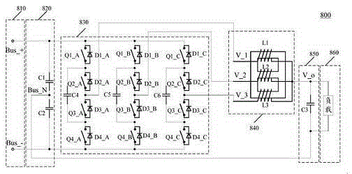
[0003] It can be seen that, in order to achieve figure 1 The topology of the multilevel inverter shown requires at least 12 switches, and the circuit structure is complex, which will not only increase the cost of the circuit, but also make the circuit control more difficult

Method used


Image

  • Inverter
  • Inverter
  • Inverter

Examples


Embodiment Construction

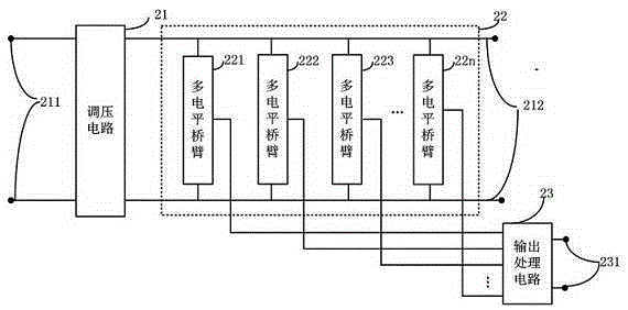
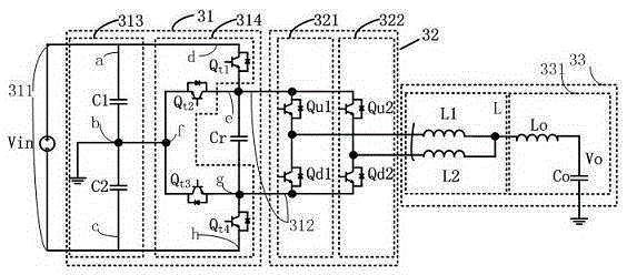
[0031] The embodiment of the present invention provides an inverter, which optimizes the three-level inverter in the known technology, uses a special voltage regulation circuit, and the multi-level bridge arm can be realized with only two switches, and in There are only two switches in the circulating current circuit of the present invention, the parasitic inductance is reduced, and the voltage peak is reduced, thereby improving the reliability of the circuit. In order to make the content of the present disclosure easier to understand, the following specific embodiments are taken as examples in which the present invention can indeed be implemented. In addition, wherever possible, components / members / steps with the same reference numerals are used in the drawings and embodiments to represent the same or similar parts.

[0032] figure 2 It is a block diagram of an embodiment of the present invention, the inverter includes a voltage regulation circuit 21, a multi-level bridge ar...


PUM


Abstract

An inverter comprises a voltage regulation circuit, a multi-level bridge arm circuit and an output processing circuit, wherein the voltage regulation circuit receives DC input voltage, converts the DC input voltage into DC output voltage through voltage regulation, and outputs the DC output voltage to the multi-level bridge arm; the multi-level bridge arm circuit carries out chopping on the DC output voltage, and the DC output voltage is overlapped to AC to be outputted via the output processing circuit; the voltage regulation circuit comprises a voltage dividing circuit and a voltage regulation bridge arm; the voltage dividing circuit divides the DC input voltage into first voltage and second voltage; the voltage regulation bridge arm outputs the first voltage to the DC output end at a positive half cycle of AC output and outputs the second voltage to the DC output end at a negative half cycle of AC output; and the voltage at the DC output end is the DC output voltage. The technical scheme of the invention provides a simple and high-efficiency three-level interleaving topology structure which can be flexibly expanded to N-phase interleaving.

Description

technical field [0001] The present invention relates to inverters, and more particularly to multilevel inverters. Background technique [0002] The general structure of the multi-level inverter is to synthesize a ladder wave in several stages to approximate the sinusoidal output voltage. Due to the increase in the number of output voltage levels of this inverter, the harmonic content of the output waveform is reduced, the voltage stress on the switch is reduced, and there is no need for a voltage equalizing circuit. Level inverter circuits, diode-clamped inverter circuits, and multi-level inverters that are mainly used in the fields of high-voltage and high-power motor speed regulation, reactive power compensation, and active filtering. Patent 201310390675.7 provides a multi-level inverter topology, such as figure 1 As shown, it is a specific embodiment of the patent, including three-way capacitor-clamped three-level bridge arms, three-level bridge arm A, three-level bridg...

Claims


Application Information

Patent Timeline
Patent Type & Authority Applications(China)
IPC IPC(8): H02M7/483
Inventor 徐明孙巨禄
Owner FSP POWERLAND TECH
Learn More