
Indoor visible light asynchronous location method using camera

A positioning method and visible light technology, applied in the field of visible light communication, can solve the problems of weak, poor scalability, complex and commercial equipment, etc., and achieve the effect of simple and easy implementation, easy implementation, and improved scalability and practicability.

Active Publication Date: 2016-02-03
BEIJING INSTITUTE OF TECHNOLOGYGY
View PDF6 Cites 12 Cited by
  • Summary
  • Abstract
  • Description
  • Claims
  • Application Information

AI Technical Summary

Problems solved by technology

[0006] The purpose of the present invention is to provide a method and system for indoor visible light positioning using a camera to solve the problems of poor scalability, complex equipment, and poor commercial availability caused by using an additional receiving module to receive LED signals in existing indoor positioning. Under the condition of directly using the self-contained camera of the smart terminal, it can perform indoor visible light positioning

Method used


Image

  • Indoor visible light asynchronous location method using camera
  • Indoor visible light asynchronous location method using camera
  • Indoor visible light asynchronous location method using camera

Examples


Embodiment 1

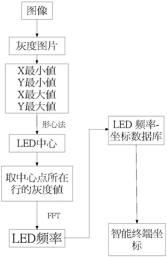
[0034] The present invention is an indoor visible light asynchronous positioning method using a camera, the process of which is as follows figure 1 As shown, the specific implementation includes the following steps:

[0035] Step 1. Assign frequency to each LED in the LED array, that is, each LED sends a periodic signal corresponding to the assigned frequency. At the sending end, a processor is used to generate a periodic signal of the assigned frequency and drive the LED to send a visible light periodic signal. ;

[0036] The LED array in step 1 refers to the collection of all LEDs for indoor visible light positioning; the periodic signal can be either a sine wave periodic signal or a square wave periodic signal; the frequency of the visible light periodic signal sent by the LED satisfies the condition that the human eye cannot see it Blinking, that is, greater than 50 Hz; signals are sent independently between different LEDs, that is, they do not affect each other;

[0037...

Embodiment 2

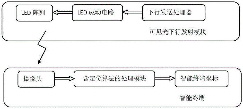
[0051] This embodiment discloses a system constructed according to the present invention "An Indoor Visible Light Asynchronous Positioning Method Using a Camera", as shown in the attached image 3 shown. Depend on image 3 It can be seen that the positioning system relied on by the method of the present invention includes two parts, the visible light downlink transmitting module and the intelligent terminal, specifically:

[0052] The visible light downlink transmission module further includes: a downlink transmission processor, an LED drive circuit and an LED array;

[0053] Wherein, in the present embodiment, the downlink sending processor adopts FPGA to generate codes and realizes, and also can adopt single-chip microcomputer to realize, and adopts a plurality of white light LEDs in the LED array, is 3 in the present embodiment;

[0054] Wherein, the single-chip microcomputer or FPGA of the downlink sending processor is used to generate the signal sent by the white light ...


PUM


Abstract

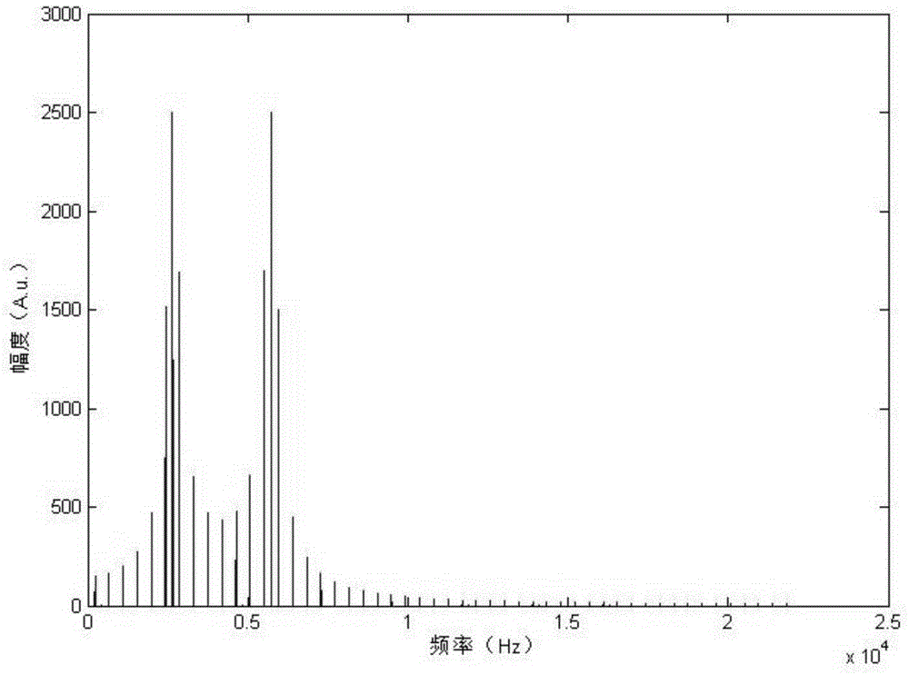
The invention relates to an indoor visible light asynchronous location method using a camera, belonging to the technical field of visible light communication. According to the technology core, a light emitting diode (LED) sends a signal asynchronously, and the indoor visible light is located by use of the camera of a smart terminal. Different frequencies of signals are applied to different LEDs, the camera of the smart terminal receives the signal sent by the LED and forms an image, and different LEDs are distinguished through algorithms, namely, a receiving end receives the signal sent by the LED and forms the image by use of the camera of the smart terminal, after the image is converted into a gray level image, fast Fourier transform is performed on gray level value data in the gray level image, LEDs sending signals of different frequencies are distinguished according to the magnitude spectrums of the Fourier transform, the positions of the LEDs are determined by use of an inlaid LED frequency-coordinate database of the smart terminal, the position of the smart terminal can be determined according to the position of the LED, so that the smart terminal realizes indoor location without extra modules.

Description

technical field [0001] The invention relates to an indoor visible light asynchronous positioning method using a camera, and belongs to the technical field of visible light communication. Background technique [0002] The indoor positioning solution based on visible light communication (VisibleLightCommunication, VLC) technology has the following two advantages: [0003] 1) The white light emitted by the semiconductor light-emitting diode (Light Emitting Diode, LED) is used as the carrier of the positioning signal, so there is no electromagnetic radiation and is not limited by the application environment; [0004] 2) The indoor positioning system based on VLC technology is compatible with the future VLC communication technology, so it does not require expensive hardware equipment investment, and the cost is relatively low. [0005] At present, there are many indoor positioning methods, but most of these positioning methods based on indoor visible light require a special rece...

Claims


Application Information

Patent Timeline
IPC IPC(8): H04B10/116
Inventor 杨爱英吕慧超冯立辉倪国强
Owner BEIJING INSTITUTE OF TECHNOLOGYGY
Learn More