Hollow single screw extruder with spiral grooves in double sides

A single-screw extruder and hollow screw technology, applied in the field of new hollow single-screw extruders, can solve the problems of different and complex structures, and achieve the effects of eliminating poor stability, shortening the length of the screw, and strengthening the drag effect.

Inactive Publication Date: 2016-02-10
SHUNDE POLYTECHNIC
View PDF5 Cites 11 Cited by
  • Summary
  • Abstract
  • Description
  • Claims
  • Application Information

AI Technical Summary

Problems solved by technology

[0005] Example 1, the patent "Coaxial Multi-screw Extruder" (publication number CN1059151C) discloses an extruder with multi-screw and multi-sleeve. The extruder described in this patent has two screws, two sleeve, but its two screw rods only have screw grooves on its outer circular surface, and its inner profile has no screw grooves, while its two sleeves have no screw grooves on its inner and outer circular surfaces. Said extruder is equipped with coaxial multi-layer material cylinder and screw rod, can extrude the material of the multi-layer different composition of wrapping simultaneously, and the technology described in the present invention is quite different, and its structure is complicated

Method used


Image

  • Hollow single screw extruder with spiral grooves in double sides
  • Hollow single screw extruder with spiral grooves in double sides
  • Hollow single screw extruder with spiral grooves in double sides

Examples


Embodiment 1

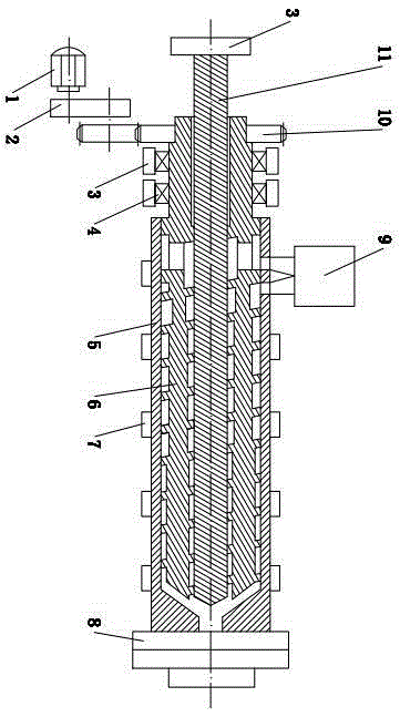
[0029] like figure 1 and figure 2 As shown, it is a hollow single-screw extruder with double-sided screw grooves, including a motor 1, a transmission mechanism 2, a seat 3, a radial thrust bearing group 4, a barrel 5, a hollow screw 6, and a heating coil 7 , extruder head 8, hopper 9, gear 10 and central shaft 11; wherein the motor 1 drives the hollow screw 6 to rotate through the transmission mechanism 2 and the gear 10, and the extruder head 8 is located at the bottom of the barrel 5 Discharge end; the hollow screw 6 is located in the barrel 5, the central shaft 11 is located in the hollow screw 6, the hollow screw 6 is coaxial with the barrel 5 and the central shaft 11 and can be rotated relative to each other. An outer helical groove 601 is arranged on the outer circular surface, and an inner helical groove 602 is arranged on the inner circular hole of the hollow screw 6; the first discharge port 901 and the second discharge port 902 of the hopper 9 are connected with th...

Embodiment 2

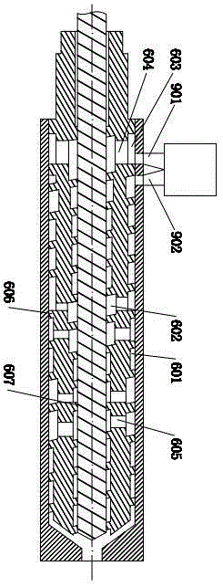
[0033] like image 3 As shown, it is a hollow single-screw extruder with double-sided screw grooves, including a motor 1, a transmission mechanism 2, a seat 3, a radial thrust bearing group 4, a barrel 5, a hollow screw 6, and a heating coil 7 , extruder head 8, hopper 9, gear 10 and central shaft 11; wherein the motor 1 drives the hollow screw 6 to rotate through the transmission mechanism 2 and the gear 10 ( image 3It is not shown in the figure, and its matching relationship is the same as that of Embodiment 1), the extruder head 8 is set at the discharge end of the barrel 5; the hollow screw 6 is located in the barrel 5, and the central shaft 11 is located in the hollow Inside the screw rod 6, the hollow screw rod 6 is coaxial with the machine barrel 5 and the central shaft 11 and can be rotated relatively. Inner spiral groove 602; the first discharge port 901 and the second discharge port 902 of the hopper 9 communicate with the left end of the inner spiral groove 602 an...

Embodiment 3

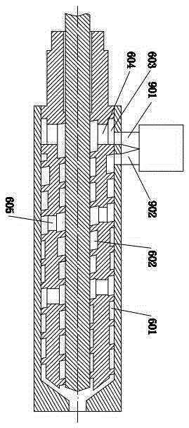
[0037] like Figure 4 As shown, it is a hollow single-screw extruder with double-sided screw grooves, including a motor 1, a transmission mechanism 2, a seat 3, a radial thrust bearing group 4, a barrel 5, a hollow screw 6, and a heating coil 7 , extruder head 8, hopper 9, gear 10 and central shaft 11; wherein the motor 1 drives the hollow screw 6 to rotate through the transmission mechanism 2 and the gear 10 ( Figure 4 It is not shown in the figure, and its matching relationship is the same as that of Embodiment 1), the extruder head 8 is set at the discharge end of the barrel 5; the hollow screw 6 is located in the barrel 5, and the central shaft 11 is located in the hollow Inside the screw rod 6, the hollow screw rod 6 is coaxial with the machine barrel 5 and the central shaft 11 and can be rotated relatively. Inner spiral groove 602; the first discharge port 901 and the second discharge port 902 of the hopper 9 communicate with the left end of the inner spiral groove 602...


PUM


Abstract

The invention relates to a hollow single screw extruder with spiral grooves in double sides. The hollow single screw extruder comprises a motor, a transmission mechanism, a base, a radial thrust bearing pack, a machine barrel, a hollow screw, an electric heating coil, an extruder head, a hopper, a gear and a central shaft. The motor drives the hollow screw to rotate through the transmission mechanism and the gear, and the extruder head is arranged at the discharge end of the machine barrel. The hollow single screw extruder is characterized in that the hollow screw is located in the machine barrel, and the central shaft is located in the hollow screw; the hollow screw is coaxial with the machine barrel and the central shaft and can rotate relative to the machine barrel and the central shaft; the outer spiral groove is formed in the outer circular surface of the hollow screw, and the inner spiral groove is formed in an inner circular hole of the hollow screw; a first discharge outlet and a second discharge outlet of the hopper are communicated with the left end of the inner spiral groove and the left end of the outer spiral groove respectively, and the right end of the outer spiral groove and the right end of the inner spiral groove are communicated with the extruder head. According to the hollow single screw extruder provided with the hollow screw, the length of the screw can be greatly reduced, the requirement of a material extrusion molding process for the relative length of a flow channel of the screw can be met sufficiently, the residence time of materials in the spiral grooves is shortened, decomposition of the high molecular materials is reduced, and product quality is guaranteed; besides, the service life of the machine can be prolonged, the productivity of the machine can be improved significantly, and the heat efficiency is improved.

Description

technical field [0001] The invention relates to a novel hollow single-screw extruder with double-sided screw grooves, which is mainly used for mixing, plasticizing and extruding polymer materials, and belongs to the technical field of polymer material molding equipment. Background technique [0002] Plastic extrusion molding machine is an important equipment for processing polymers. After polymers (granules, powders, etc.) enter the barrel and screw groove space through the hopper, they move forward under the push of the screw flight. Every time the screw rotates, The material moves forward by a lead, and the material has to go through a series of processes such as plasticizing and melting in the screw groove. Its shape changes from the initial solid state to the molten state through many links such as plug flow, molten film, circulation and solid phase crushing. state, and then molded into plastic products through machine heads, molds and other equipment. [0003] Obviousl...

Claims


Application Information

Patent Timeline
Patent Type & Authority Applications(China)
IPC IPC(8): B29C47/38B29C47/60B29C48/395
CPCB29C48/397B29C48/51
Inventor 陈学锋凃明霞徐言生胡建国柯美元曾宪荣
Owner SHUNDE POLYTECHNIC
Why Eureka
Try Eureka