
Power-line repairing device

A technology for electric emergency repair and driving device, which is applied in transportation and packaging, cleaning of open water surfaces, ships, etc., can solve the problems of general oil absorption effect, high cost, and the need for high-power engines, and achieves good oil absorption effect and high oil absorption rate. Effect

Inactive Publication Date: 2016-02-10
钮振伟
View PDF9 Cites 2 Cited by
  • Summary
  • Abstract
  • Description
  • Claims
  • Application Information

AI Technical Summary

Problems solved by technology

This kind of centrifugal oil suction vessel has the functions of automatic oil suction and oil rejection (oil collection), which saves manpower, but has the following obvious shortcomings: 1. The conveyor belt only relies on its own oil-friendly and non-hydrophilic characteristics and the ability to press oil pollution into the bottom Oil is sucked under high pressure, but it cannot be completely and completely absorbed. After the centrifugal oil suction ship passes, a large amount of oil will still be left on the water surface to form "oil leakage"; Very high, that is, the speed of the conveyor belt is very high, which not only reduces the oil absorption effect, forms a large amount of "oil leakage", but also requires a high-power engine, which will inevitably result in high costs; It is a ray tangent to the conveyor belt at the turning point, and these rays are ray clusters that slope upwards from the horizontal plane around the turning point of the conveyor belt, and the trajectory of the oil that can be thrown into the oil collection tank is only a pole of the above-mentioned trajectory ray clusters. A small part, therefore, the oil pollution is not only thrown upwards into the oil collection tank, but more oil pollution is thrown backwards to the water surface behind the ship to form a large amount of "leaked oil", that is to say, the centrifugal oil pollution cleaning ship The oil absorption effect is average
However, the ship has the following disadvantages: 1. Because the oil-absorbing roller relies on its own rolling to press the oil into the natural contact of the water to absorb oil, the oil-absorbing roller cannot guarantee that all the encountered oil will be absorbed, and the oil is not completely absorbed. There are many "oil leaks", and the oil absorption effect and efficiency are poor; 2. When the scraper scrapes the oil-absorbing roller, the oil on the side (outside) of the oil-absorbing roller adjacent to the scraper will flow into the oil flow groove along the scraper, but the other side of the oil-absorbing roller The oil squeezed out from the side (inner side) will flow along the inner wall of the oil suction roller and cannot be scraped off by the scraper, thus forming "oil reservoir" or "bottom oil". The oil absorption effect of the stroke, and this part of the "oil reservoir" may flow out along the two ends of the inner cavity of the oil absorption roller to form "oil leakage"; 3. In this patent, the oil scraped in the oil flow ditch flows out of the oil by its own gravity groove, but because the oil is viscous, the oil scraped by the scraper will adhere to the inner wall of the oil flow groove after entering the oil flow groove; because the conveyor belt where the oil flow groove is located is rotating in a cycle, it is not equal to the inside of the oil flow groove The oil will be sent to the oil suction roller by the conveyor belt to scrape the oil again. Obviously, the scraping effect of the scraper will become worse and worse, and even the oil accumulated in the oil flow channel will be squeezed onto the oil suction roller. Scraping the oil-absorbing roller becomes oiling the oil-absorbing roller; 4. As can be seen from the drawings, the scrapers are arranged at intervals on the conveyor belt, so there will be two situations. 1. If the rotation speed of the scraper or the conveyor belt is slow, only The oil in the oil-absorbing roller corresponding to the scraper can be scraped off, but the oil in the oil-absorbing roller corresponding to the conveyor belt between two adjacent scrapers cannot be scraped off, which forms a blind spot for scraping oil, which will turn to the On the surface of the water, not only does it not absorb oil, but it may also flow the absorbed oil into the water, greatly reducing the oil absorption efficiency and effect. Second, if the speed of the scraper and the conveyor belt is much higher than the speed of the oil suction roller, the fast alternate scraper can eliminate the above blind spots, but in this way Not only will it increase the wear and tear of the scraper on the oil-absorbing roller, but also the oil in the oil-flowing ditch will be scratched against the oil-absorbing roller again without time to flow out, which will also cause the disadvantages of oil delivery like the oil-absorbing roller; 5. In order to achieve better The oil scraping effect will inevitably increase the extrusion force between the scraper and the oil-absorbing roller, which will inevitably increase the scraping and wear of the scraper on the oil-absorbing roller, and the oil-absorbing roller needs to be replaced frequently, which is not only troublesome to maintain, but also inevitably increases the cost
[0006] The above two patents also have a common shortcoming, that is, there is no function of adjusting the height of the oil-absorbing roller or the conveying belt, so that as the oil-absorbing continues, the total weight of the hull will inevitably increase, and more parts of the oil-absorbing roller or conveying belt will be immersed in water. , so that the oil absorption roller or conveyor belt cannot be in the best oil absorption state, and the working state is unstable, that is to say, the oil absorption effect will become worse and worse

Method used


Image

  • Power-line repairing device
  • Power-line repairing device
  • Power-line repairing device

Examples


Embodiment Construction

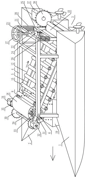
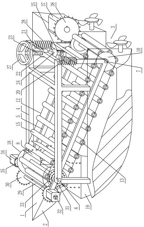
[0044] As shown in the figure, the electric emergency repair device includes a hull 1 , two water tanks 2 arranged at intervals are arranged under the hull 1 , and a gap 3 is formed between the two water tanks 2 . A loading frame 4 is installed on the hull 1, and the loading frame 4 can be loaded with electric power emergency repair equipment and tools, such as climbing tools, cables, various power replacement parts of substations, inspection and maintenance tools, and the like. In this way, during electric emergency repairs, not only can equipment, tools and personnel be quickly transported to ensure timely arrival at the emergency repair site, but also the hull and loading frame floating on the water surface also provide maintenance personnel with climbing tools, which can quickly ascend and climb without climbing poles. Emergency repair greatly improves the efficiency of emergency repair.

[0045] The front part of the loading frame 4 is hinged with a tilting frame 5 corres...


PUM


Abstract

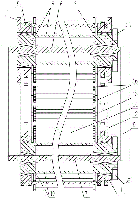
The invention discloses a power-line repairing device. The power-line repairing device comprises a ship and is structurally characterized in that a gap is formed below the ship, an inclined frame which corresponds to the gap and is provided with the high front portion and the low back portion is hinged to the front portion of a loading frame of the ship, an inclination adjusting device for adjusting the inclination degree of the inclined frame is installed between the back portion of the loading frame and the back end of the inclined frame, the front end and the back end of the inclined frame are each provided with an upper roller and a lower roller, each upper roller and the corresponding lower roller which are arranged on one side are sleeved with an annular conveying belt in a transmitting mode, and transversely-arranged inter-belt shafts are correspondingly connected between the two conveying belts and rotationally sleeved with a felt frame. By means of the power-line repairing device, power-line repairing can be assisted, oil can be thoroughly, completely and stably absorbed, the amount of missed oil is small, deoiling is thorough and complete, recycling efficiency is high, the oil absorption effect is good, operation and maintenance are easy, and cost is low.

Description

technical field [0001] The invention relates to an electric emergency repair device. Background technique [0002] With the rapid development of industrialization in various countries, the greenhouse effect continues to intensify, leading to global climate change. In the past two years, extreme climates have emerged in my country. For example, in the south, the rainfall is seriously less than in the same period of previous years, and the long-term drought has caused rivers to cut off water and flow. However, in the north, there have been frequent heavy rains for many days, causing rivers and lakes to surge, resulting in floods. It is not uncommon for surrounding substations to be flooded, damaged, and even cities to be flooded, which brings great difficulties to power repairs. [0003] For power systems, the impacts of extreme weather are generally: 1. Substation flooding affects inspection and maintenance; 2. Transformers are damaged, oil leaks, unable to work, and cause po...

Claims


Application Information

Patent Timeline
Patent Type & Authority Applications(China)
IPC IPC(8): B63B35/32E02B15/10
CPCY02A20/204
Inventor 钮振伟
Owner 钮振伟
Learn More