Angular acceleration detector based on resonant light tunneling effect and detecting method

A technology of angular acceleration and tunneling effect, which is applied in the direction of velocity/acceleration/shock measurement, measurement of acceleration, instruments, etc. It can solve the problems that the temperature performance of the fiber optic gyroscope is greatly affected, and the accuracy of angular acceleration measurement is limited.

Active Publication Date: 2016-02-10
山西清众科技股份有限公司
View PDF8 Cites 1 Cited by
  • Summary
  • Abstract
  • Description
  • Claims
  • Application Information

AI Technical Summary

Problems solved by technology

However, the fiber ring, the core component of the fiber optic gyroscope, has a great influence on the temperature performance of the fiber optic gyroscope due to the different thermal stresses at different temperatures, which limits the accuracy of angular acceleration measurement.

Method used


Image

  • Angular acceleration detector based on resonant light tunneling effect and detecting method
  • Angular acceleration detector based on resonant light tunneling effect and detecting method
  • Angular acceleration detector based on resonant light tunneling effect and detecting method

Examples


Embodiment 1

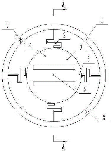
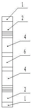
[0062] like Figure 1-3 As shown, an angular acceleration detector based on resonant optical tunneling effect, including a ring-shaped fixed frame 1, an elastic cantilever beam 2 and a mass block 3,

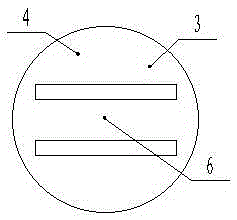
[0063] The mass block 3 is composed of a refraction unit 4, a connection unit 5 and a resonance unit 6, the number of the refraction unit 4 and the connection unit 5 is two, the resonance unit 6 and the two connection units 5 are connected to form an I-shaped structure, and two The connection unit 5 is two parallel beams of an I-shaped structure, the square faces of the two refraction units 4 are opposite and connected by the I-shaped structure, the resonance unit 6 is parallel to the square faces of the refraction unit 4; the refraction unit 4, the connection unit 5 Two gaps are formed between the resonance unit 6 and two tunneling layers; the mass block 3 is etched from a circular silicon wafer; the curves of the outer contours of the two refraction units 4 belong to the same c...

Embodiment 2

[0067] Taking the angular acceleration detector of Embodiment 1 as an example, the position of the adjustable light source relative to the outer frame is fixed, the incident light wavelength of the adjustable light source is 1550nm, and the incident light is P (or S) polarized light, and the incident direction is relatively kept constant. There are four elastic cantilever beams 3 and 4, the four elastic cantilever beams are distributed in a cross, one end is respectively connected around the outer surface of the mass block 5, and the other end is fixed on the inner wall of the fixed frame 6;

[0068] The mass block is made of silicon, whose refractive index is n si =3.42 (applicable to infrared incident light), completed by integrated photolithography technology; the position of the photodetector relative to the outer frame is fixed, and the response band of the photodetector should include the wavelength of the light source. After the incident light passes through the mass bl...


PUM


Abstract

The invention relates to an angular acceleration detector based on a resonant light tunneling effect theory and a detecting method and provides a novel-structure angular acceleration detector for detecting an angular acceleration by virtue of the characteristic of high resolution of a resonant light tunneling effect. The adopted technical scheme is as follows: the angular acceleration detector based on the resonant light tunneling effect comprises an annular fixed frame, elastic cantilever beams, a mass, an adjustable light source and a photoelectric detector. The variable quantity of high transmitted intensity T, caused by variation of weak transfer quantity of the mass, is detected by virtue of the resonant light tunneling effect, and the angular variable quantity is obtained through the change of the monitored light transmitted intensity, so that the micro angular variable quantity is precisely measured.

Description

technical field [0001] The invention relates to an angular acceleration detector, in particular to an angular acceleration detector and a detection method based on the principle of resonant light tunneling effect. Background technique [0002] At present, angular accelerometers are inertial sensors used to measure the angular acceleration of moving objects, and have been used in many fields, such as rollover warning detection devices for cars to protect passenger safety, flight status detection of aircraft, and robot design. With the rapid development of micro-electro-mechanical systems (MEMS) technology, micro-mechanical gyroscopes are developing towards low power consumption, easy integration, miniaturization, high sensitivity, and low cost. However, due to the imperfection of micromechanical theory and technology, micromechanical gyroscopes are still low-to-medium precision inertial sensors. Among them, the drift error and machining accuracy caused by the ambient tempera...

Claims


Application Information

Patent Timeline
Patent Type & Authority Applications(China)
IPC IPC(8): G01P15/093
Inventor 菅傲群段倩倩魏重光桑胜波张文栋唐军石云波
Owner 山西清众科技股份有限公司
Why Eureka
Try Eureka