Drive device and electric power steering device including drive device

A technology of driving device and driving element, applied in the field of electric power steering equipment and driving device, can solve the problem of increasing the number of parts, and achieve the effect of reducing product volume and small product volume

Active Publication Date: 2016-02-10
DENSO CORP
View PDF8 Cites 15 Cited by
  • Summary
  • Abstract
  • Description
  • Claims
  • Application Information

AI Technical Summary

Problems solved by technology

Therefore, the structure in Patent Document 1 requires an opening in the case, and the heat sink must be provided in a part separated from other parts, which increases the number of parts in the drive device.

Method used


Image

  • Drive device and electric power steering device including drive device
  • Drive device and electric power steering device including drive device
  • Drive device and electric power steering device including drive device

Examples


no. 1 example

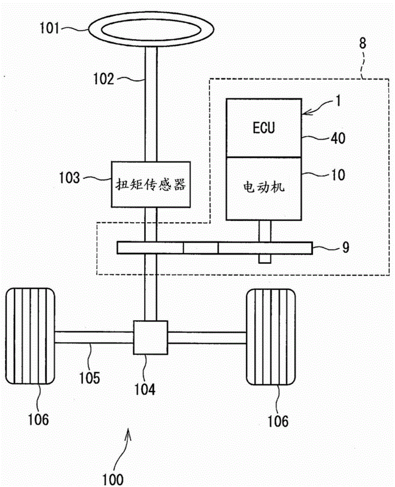
[0033] exist Figure 1 to Figure 11 The driving device and the electric power steering apparatus in the first embodiment of the present disclosure are shown in . Hereinafter, in all the embodiments described below, the same reference numerals represent the same components for the purpose of concise description.

[0034] Such as figure 1 As shown, the drive device 1 is applied to an electric power steering apparatus 8 to assist a steering operation by a driver. The drive device 1 is an integral combination of an electric motor 10 serving as a rotating electric machine and an ECU 40 serving as a controller for controlling the electric motor 10 .

[0035] figure 1 A system diagram of a steering system 100 with an electric power steering system 8 is shown. The steering system 100 includes a steering wheel 101 , a column shaft 102 , a pinion 104 , a rack shaft 105 , wheels 106 , and an electric power steering device 8 , etc., which serve as components of the system, respectivel...

no. 2 example

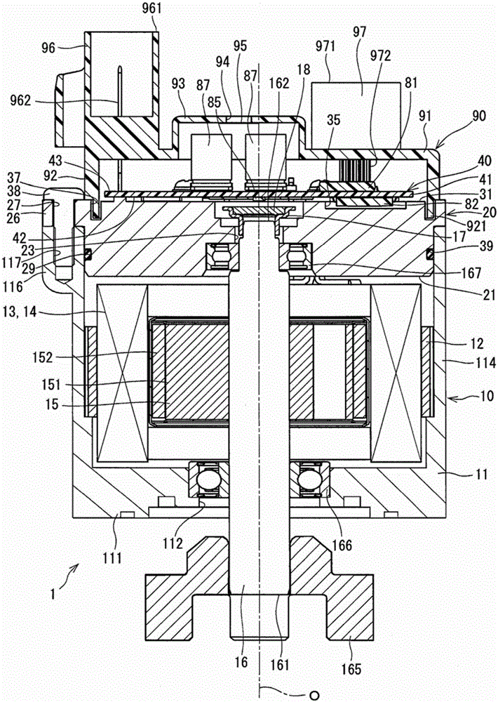
[0191] exist Figure 14 to Figure 19 The driving device in the second embodiment of the present disclosure is shown in . Figure 14 is along Figure 17 Cross-sectional view of line XIV-XIV in.

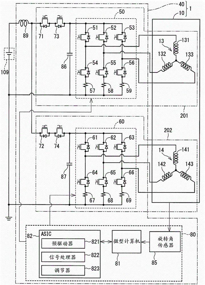
[0192] The driving device 2 is provided with a motor 210 serving as a rotating motor, a front frame end 215, a rear frame end 220, an ECU 240 serving as a controller, a connector 280, a cover member 290, and the like. In the present embodiment, the rear frame end 220 corresponds to a "frame member". The electrical configuration of the driving device 2 is the same as that of the above-described embodiment, so that a repeated description will not be provided.

[0193] The motor 210 is set as Figure 14 Stator 212, rotor 15, shaft 16 and other parts are shown.


PUM


Abstract

A drive device that includes a rotating electric machine having a stator with a winding wound on the stator, a rotor rotatably disposed relative to the stator, and a shaft rotating together with the rotor. The drive device also includes a frame member fixed on the rotating electric machine. The drive device further includes a circuit board fixed on the frame member, with a first surface of the circuit board on a frame member side serving as a heat generation element mount surface. The drive device also has a drive element located on the first surface of the circuit board in a heat dissipatable manner, and serving as a component of an inverter that switches on and off to supply an electric current to the winding.

Description

technical field [0001] The present disclosure generally relates to a drive device and an electric power steering apparatus including the drive device. Background technique [0002] Generally, an electric motor and an inverter for controlling the driving of the electric motor are arranged at positions close to each other. For example, Japanese Patent Laid-Open Publication No. 2003-153552 (Patent Document 1) discloses a structure in which a circuit board on which an inverter is mounted is accommodated in a housing and the housing is attached to a casing of a compressor. [0003] The structure in Patent Document 1 has a heat sink provided on the opening of the case, and heat from (IMP) is dissipated to the heat sink. Therefore, the structure in Patent Document 1 requires an opening in the case, and the heat sink must be provided in a part separate from other parts, which increases the number of parts in the drive device. Contents of the invention [0004] It is an object of...

Claims


Application Information

Patent Timeline
Patent Type & Authority Applications(China)
IPC IPC(8): H02K11/00B62D5/04
CPCH02K5/1732H02K5/225H02K11/33B62D5/0406H02K9/223B62D5/0412B62D5/0463H02K9/00H02K11/21H02K11/30
Inventor 株根秀树
Owner DENSO CORP
Why Eureka
Try Eureka