Channel type thickener

A thickener and canal-type technology, applied in the sedimentation tank and other directions, can solve the problems that restrict the application of small and medium-sized mineral processing enterprises, the concentration of tailings in the mineral processing plant is not high, and the consumption of electricity and water is large. Energy saving effect

Inactive Publication Date: 2016-02-17
黄武
View PDF0 Cites 0 Cited by
  • Summary
  • Abstract
  • Description
  • Claims
  • Application Information

AI Technical Summary

Problems solved by technology

[0002] The concentration of tailings in the concentrator is generally not high. If it is discharged directly to the tailings pond, it will consume a lot of power consumption of the mortar pump and the efficiency is low. Therefore, it is necessary to concentrate the tailings
At present, the commonly used concentration treatment equipment is the thickener, but the traditional "round pool" thickener has a large volume, a large area, and high equipment costs, which restrict its application in small and medium-sized mineral processing enterprises. From the perspective of economic rationality, it is generally used less, and basically adopts the direct discharge method, which consumes a lot of electricity and water, and belongs to extensive production.

Method used


Image

  • Channel type thickener

Examples


Embodiment 1

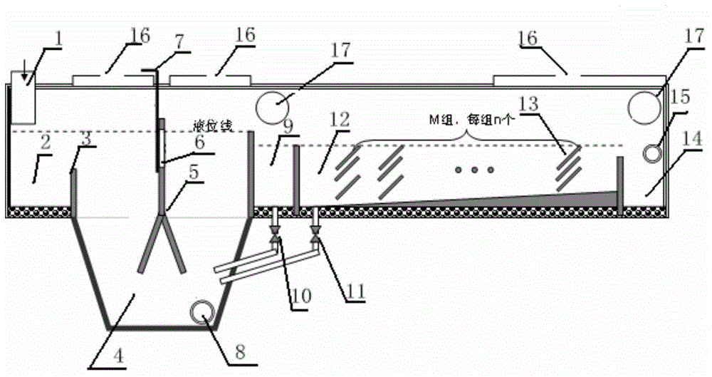
[0026] figure 1 It is an internal structure diagram of a channel thickener of the present invention, and the connection relationship and working principle between each component are as follows:

[0027] The ore pulp enters the receiving tank 2 through the feeding port 1, and crosses the partition 3, and the heavy particles in the pulp settle in the thickening tank 4. The dense pool 4 is divided into left and right parts by the gable frame 5, and the tortuosity of the water flow is increased by the gable frame 5 and the settlement height is reduced, so as to accelerate the settlement. A water-permeable window 6 is installed on the gable frame 5 to adjust the ratio of the flow rate of the upper and lower channels. The adjustment method is to adopt the gate valve 7. The settled heavy particles are discharged through the outlet 8 in the form of high-concentration slurry. The unsettled fine mud enters the buffer tank 9, where it is further settled by gravity. The settled fine s...

Embodiment 2

[0030] Dense Drain Calculation

[0031] Note: The pulp flow rate is recorded as G(m 3 / h) The settling velocity of mud in the slurry is denoted as V 1 (m / s); the horizontal running speed of the pulp is denoted as V 2 (m / s); the settlement height is recorded as H(m); the settlement time is recorded as t(s); the water level height of the dense channel is recorded as h(m), the depth channel width is recorded as b(m); the length of the dense channel is recorded as L(m); the number of each set of settling sloping plates in the channel body. Then there is the following relationship:

[0032] V 1 =0.3×10 -3 m / s (experimental data)

[0033] V 2 =G / (3600bh)

[0034] t=H / V 1 =(h / n) / V 1

[0035] L=tV 2

example

[0037] Take tailings discharge in iron concentrator as an example: Assume that the amount of tailings discharged in each iron concentrator is G=120m 3 / h, the concentration is 15%. Assuming that the canal width b=1m, the canal water level height h=1m, and the number n=10 of each set of sloping plates, it can be calculated as follows:

[0038] V 2 =G / (3600bh)=120 / (3600×1×1)=0.033333m / s

[0039] t=H / V 1 =(h / n) / V 1 =(1 / 10) / (0.33×10 -4 ) = 3030s

[0040] L=tV 2 =3030×0.033333=101m

[0041] If the HRC type high-pressure thickener is selected, the required area is at least 12m 2 , with a height of about 10m and a huge volume. If the channel-type thickener is used, although the length increases a lot, reaching 101m, but because of the linear arrangement, it will not take up too much space in the factory area, and the structure of the channel-type thickener is simple, there are basically no mechanical moving parts, and the operation and maintenance are very convenient.


PUM


Abstract

The invention provides a channel type thickener. The thickener comprises a thickening pool, a settling basin, a desilting valve and a mud cleaning valve; wherein an upper part of the thickening pool comprises a buffer pool, which is connected to the settling basin; one end of the desilting valve is communicated with a bottom part of the buffer pool, and the other end of the desilting valve is communicated with an outlet at a lower part of the thickening pool; one end of the mud cleaning valve is communicated with the front end of the bottom of the settling basin, and the other end is communicated with the outlet at the lower part of the thickening pool; liquid at the upper part of the settling basin is communicated with a drainage hole. The thickening pool, the buffer pool, the settling basin, the desilting valve and the mud cleaning valve are arranged linearly in order for condensation and treatment of tailings, and the separated clear water can be discharged or recycled for utilization on-site. The thickener has the advantages of simple structure and saved space, so that power saving and water saving are realized.

Description

technical field [0001] The invention relates to a channel-type thickener suitable for treating tailings in a mineral processing plant, which belongs to the field of industrial energy saving. Background technique [0002] The concentration of tailings in the concentrator is generally not high. If it is discharged directly to the tailings pond, it will consume a lot of power consumption of the mortar pump and the efficiency is low. Therefore, it is necessary to concentrate the tailings. At present, the commonly used concentration treatment equipment is the thickener, but the traditional "round pool" thickener has a large volume, a large area, and high equipment costs, which restrict its application in small and medium-sized mineral processing enterprises. From the perspective of economic rationality, it is generally used less, and basically adopts the direct discharge method, which consumes a lot of electricity and water, and belongs to extensive production. Contents of the ...

Claims


Application Information

Patent Timeline
Patent Type & Authority Applications(China)
IPC IPC(8): B01D21/02
Inventor 黄武
Owner 黄武
Why Eureka
Try Eureka