
Energy-saving type hydraulic station

A hydraulic station, energy-saving technology, applied in the direction of fluid pressure actuating devices, servo motors, servo motor components, etc., can solve the problems of large power consumption, unfavorable energy conservation and environmental protection, waste, etc., to improve conversion efficiency and reduce usage. , the effect of reducing energy

Inactive Publication Date: 2016-02-17
李朝明 +1
View PDF6 Cites 4 Cited by
  • Summary
  • Abstract
  • Description
  • Claims
  • Application Information

AI Technical Summary

Problems solved by technology

However, the process of driving the oil pump by the motor consumes a lot of electric energy. In the process of converting electric energy into oil pressure by the electric motor oil pump, most of the electric energy is consumed by converting into mechanical energy, and the conversion into useful pressure energy is very small, so it is very wasteful. The future development path that is not conducive to energy conservation and environmental protection

Method used


Image

  • Energy-saving type hydraulic station
  • Energy-saving type hydraulic station

Examples


Embodiment 1

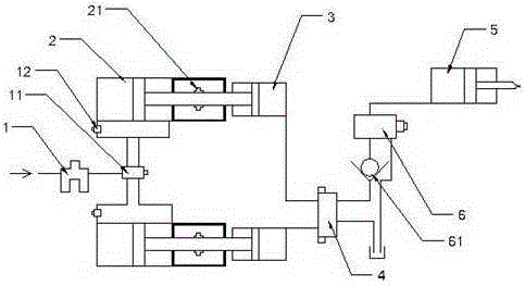
[0017] Embodiment 1 is basically as attached figure 1 Shown:

[0018] The energy-saving hydraulic station is installed on the driving end of the tooling fixture, including the hydraulic cylinder 5 connected with the tooling equipment, and also includes two oil cylinders 3, two cylinders 2, control valve 4, and reversing valve 6. The two cylinders 2 are connected with With the same air source device, the output rod of cylinder 2 is connected to the piston of cylinder 3, the oil circuit input end of oil cylinder 3 is connected to the oil tank through control valve 4, and the oil circuit output end of oil cylinder 3 is connected to control valve 4 and reversing valve 6 , the reversing valve 6 is connected with the hydraulic cylinder 5, and the hydraulic cylinder 5 completes the driving of a series of tooling equipment.

[0019] Both the reversing valve 6 and the control valve 4 are equipped with oil return pipes connected to the oil tank, and the oil pipe between the reversing v...

Embodiment 2

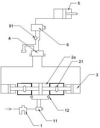
[0022] Embodiment 2 is basically as figure 2 Shown:

[0023] The difference from Example 1 is that the two cylinders 2 in Example 1 are replaced by a double-headed cylinder 2a, and the two output rods of the double-headed cylinder 2a are respectively connected to the piston of the oil cylinder 3, and two oil cylinders 3 and double-headed cylinders are used. The combination of the cylinders 2a is driven, and the oil cylinder 3 can be replaced for continuous driving when the oil cylinder 3 reaches a critical point, so that the hydraulic system is more stable. Limiting blocks 21 are respectively provided on the two output rods of the double-headed cylinder 2a, and the area of ​​the limiting blocks 21 is larger than the area of ​​the through hole passing through the two ends of the output rod.


PUM


Abstract

The invention relates to the technical field of fixtures and discloses an energy-saving type hydraulic station. The energy-saving type hydraulic station is located at the driving end of a fixture and comprises a hydraulic cylinder connected with tool equipment. The energy-saving type hydraulic station further comprises an air cylinder set, a control valve, a reversing valve and two or more oil cylinders. The air cylinder set is connected with the same air source device and provided with a plurality of output rods. Each output rod of the air cylinder set is connected with the driving faces of pistons of the oil cylinders. Oil path output outlets of all the oil cylinders are connected with the control valve through oil paths. The control valve, the reversing valve and the hydraulic cylinder are sequentially connected through an oil path. Compared with a traditional hydraulic system, the energy conversion efficiency is improved through the scheme. Meanwhile, due to the fact that hydraulic oil does not pass through an oil pump, the loss of the hydraulic oil due to the oil pump is not increased, and the usage amount of the hydraulic oil is reduced. A motor used by a common hydraulic station is not used, so that the energy consumed by the motor is reduced, and the requirements for oil products are low at the same time.

Description

technical field [0001] The invention relates to the technical field of fixtures. Background technique [0002] Tooling, that is, process equipment: refers to the general term for various tools used in the manufacturing process, including knives, fixtures, molds, measuring tools, inspection tools, auxiliary tools, fitter tools, station equipment, etc. The hydraulic station is often used in the tooling, which can clamp the fixture and propel the mold, measuring tool, machine tool, etc. Since the hydraulic system realizes the force transmission through the oil circuit, the operation process is relatively stable and has a certain buffering effect, avoiding Hard collisions between parts or workpieces cause damage to parts or workpieces. [0003] At present, the hydraulic system mainly includes a hydraulic cylinder, a control valve, and an oil pump connected in sequence through the oil circuit. The oil pump is driven by a motor, and the oil pump outputs high-pressure oil to trans...

Claims


Application Information

Patent Timeline
Patent Type & Authority Applications(China)
IPC IPC(8): F15B11/072F15B11/20F15B13/06F15B15/24
Inventor 李朝明李富平
Owner 李朝明
Learn More