
Hand-held absorbing material reflectance measuring device

A technology of wave absorbing material and measuring device, which is applied in the field of handheld wave absorbing material reflectivity measuring device, can solve the problems of complicated installation and debugging, poor positioning angle accuracy of receiving and transmitting antennas, heavy weight, etc., and achieves convenient and accurate angle control. , to ensure the test accuracy, the effect of easy and precise processing

Active Publication Date: 2018-03-20
成都恩驰微波科技有限公司
View PDF8 Cites 0 Cited by
  • Summary
  • Abstract
  • Description
  • Claims
  • Application Information

AI Technical Summary

Problems solved by technology

There are following disadvantages based on this method: 1. The horn antenna and the supporting bow frame and its driving motor have high cost, large volume, heavy weight, complicated installation and debugging, and relatively low accuracy in positioning angles of receiving and transmitting antennas. Poor; 2. The sample to be tested needs to be placed in a uniform plane wave area, and the plane wave area radiated by the horn antenna is located in the radiation far field area; at the same time, the distance R between the receiving and transmitting antennas via the material reflection path must meet the following conditions:
Due to the large diameter of the horn antenna, its radiation far-field area is far away from the antenna, resulting in a large test space; The back and forth reflection of the ground around the test system will generate a large interference signal, so a layer of high-performance absorbing material needs to be laid on the ground around the test system to reduce the background reflection of the test system, which also increases the test space and cost; 4. When the absorbing material to be tested has been coated on missiles, aircraft and ships, the traditional test system cannot be tested

Method used


Image

  • Hand-held absorbing material reflectance measuring device
  • Hand-held absorbing material reflectance measuring device
  • Hand-held absorbing material reflectance measuring device

Examples


Embodiment Construction

[0036] Embodiments of the present invention are described below through specific examples, and those skilled in the art can easily understand other advantages and effects of the present invention from the content disclosed in this specification. The present invention can also be implemented or applied through other different specific implementation modes, and various modifications or changes can be made to the details in this specification based on different viewpoints and applications without departing from the spirit of the present invention.

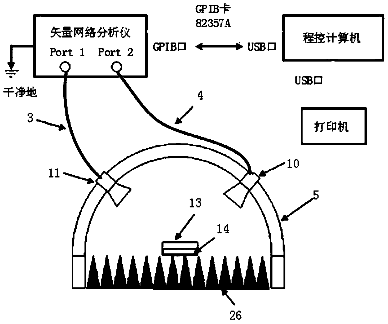
[0037] figure 1 is a schematic diagram of the traditional bow method test system, wherein, 5 is a bow guide rail, 10 is a receiving antenna, 11 is a transmitting antenna, both the receiving antenna and the transmitting antenna are horn antennas, 13 is a sample to be tested or a standard sample, 14 is a metal test platform, 26 is the background wave-absorbing material.

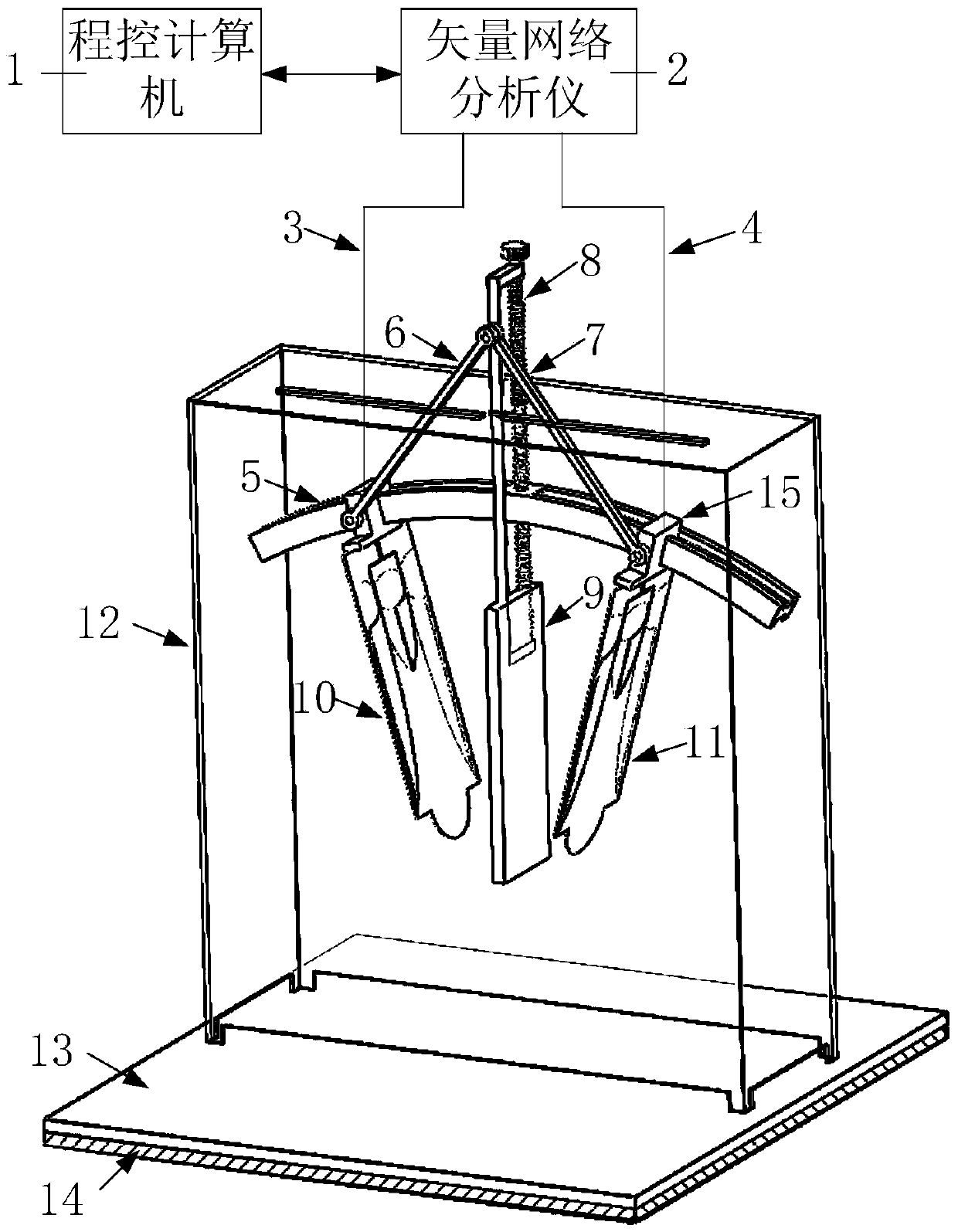
[0038] Such as Figure 2-Figure 5 As shown, the present embodim...


PUM


Abstract

The invention provides a handheld reflectance measuring device for absorbing materials, including: a metal test platform, a sample to be tested or a standard sample, a support cover, a bow-shaped guide rail, a near-field focusing antenna, a wave-absorbing partition, a slider, a lifting rod, Push-pull rod, transceiver module; the present invention adopts the near-field focusing antenna—the new double-heel structure Vivaldi antenna to replace the horn antenna as the receiving and transmitting antenna. Gain, low side lobe characteristics, can generate near-field linearly polarized plane waves, simulate the far-field radiation environment in the near field, and move the test area from the far-field area of ​​the antenna to the near-field area of ​​the antenna, reducing the test space. The distance between the test sample and the antenna is shortened, and the electromagnetic wave can irradiate the test sample more concentratedly, which reduces the influence of background reflection on the test accuracy; at the same time, the incident and reflection angles of electromagnetic waves can be adjusted precisely, which improves the accuracy of the positioning angle of the receiving and transmitting antennas. performance, reducing the operational complexity.

Description

technical field [0001] The invention relates to the field of reflectivity measurement of absorbing materials, in particular to a method that can reduce the test space and operation complexity while ensuring the test accuracy, and is suitable for on-site testing of absorbing materials coated on metal surfaces. Hand-held device for measuring the reflectivity of absorbing materials. Background technique [0002] With the rapid development of high technology, absorbing materials have been widely used. In order to study the absorbing material in depth, we need to find a method that can measure the absorbing performance of the absorbing material more accurately. The commonly used methods for testing the reflectivity of the absorbing material are RAM (Radar Absorbing Material) reflectivity far-field RCS (Radar Absorbing Material) Cross Section) test method, RAM reflectance sample space translation test method, RAM reflectance bow test method, etc. Among them, the bow test method i...

Claims


Application Information

Patent Timeline
Patent Type & Authority Patents(China)
IPC IPC(8): G01N22/00
CPCG01N22/00
Inventor 张云鹏李恩曾梦薇陈亮亮郑虎郭高凤高勇
Owner 成都恩驰微波科技有限公司
Features
  • Generate Ideas
  • Intellectual Property
  • Life Sciences
  • Materials
  • Tech Scout
  • Unparalleled Data Quality
  • Higher Quality Content
  • 60% Fewer Hallucinations
Learn More