Preparation method of electrode, and apparatus

A technology for preparing devices and electrodes, which is applied in the field of electrode preparation, and can solve problems such as slurry leakage, affecting coating quality, and uneven coating

Inactive Publication Date: 2016-02-24
INST OF ELECTRICAL ENG CHINESE ACAD OF SCI
View PDF4 Cites 8 Cited by
  • Summary
  • Abstract
  • Description
  • Claims
  • Application Information

AI Technical Summary

Problems solved by technology

One of the characteristics of this electrochemical energy storage device is that the negative electrode needs to be pre-embedded with some lithium, so the electrode needs to use a current collector with regular pores running through the upper and lower surfaces. Leakage, causing uneven coating and affecting coating quality
Although the slurry coating problem can be solved by further reducing the pore size, this will greatly increase the manufacturing difficulty and cost of the current collector.

Method used


Image

  • Preparation method of electrode, and apparatus
  • Preparation method of electrode, and apparatus
  • Preparation method of electrode, and apparatus

Examples


preparation example Construction

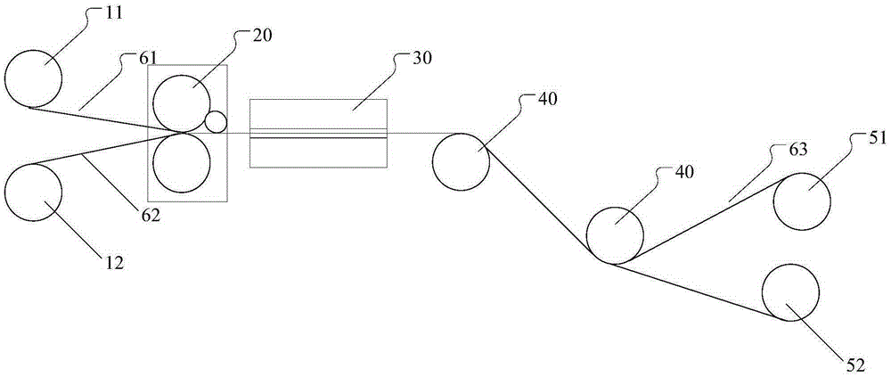
[0033] Electrode preparation equipment such as image 3 shown. When the coating device 20 is used to coat the first surface of the pole piece, the current collector unwinding device 11 and the flexible substrate unwinding device 12 are unwound synchronously, and the tension device 40 is used to make the back of the current collector 61 closely adhere to the flexible substrate 62 synchronously After the slurry is applied to the surface of the current collector 61, it enters the drying device 30, and after drying, the pole piece 63 and the flexible base 62 are respectively wound up by the pole piece winding device 51 and the flexible base winding device 52; On the second side of the current collector, since the holes on the current collector have been blocked by the slurry, there will be no material leakage, and the coating does not need to be attached to the flexible substrate.

[0034] The coating device can adopt transfer coating, knife coating or spray coating, and the dryi...

Embodiment 1

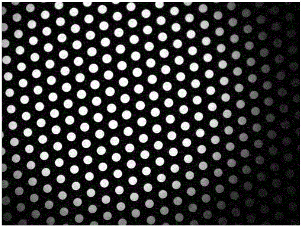
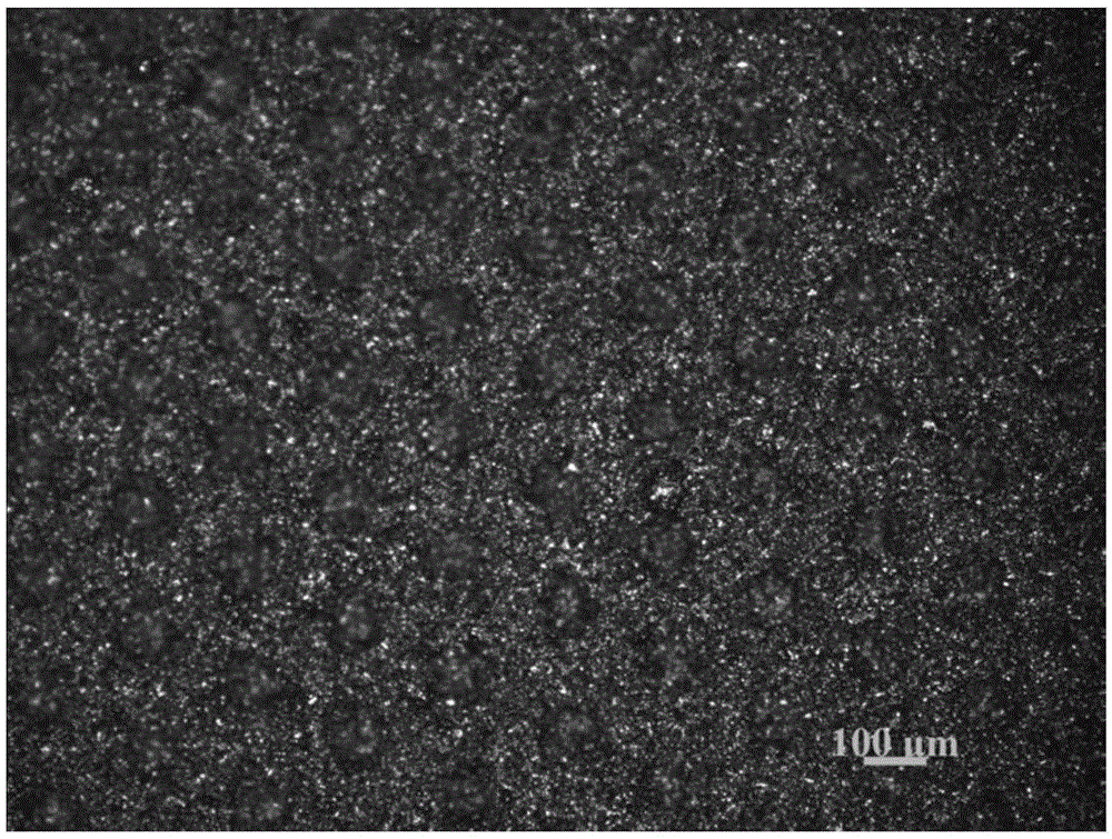
[0037] Dissolve 5 parts by mass of polyvinylidene fluoride into 125 parts by mass of N-methylpyrrolidone, add 90 parts by mass of artificial graphite CAG-3MT and 5 parts by mass of conductive carbon black SuperP, mix well and apply to copper foil After fully drying, the negative electrode is obtained. The copper foil has through-holes with a 25% porosity and a diameter of 100 μm. When the first surface is coated, a copper foil with a thickness of 8 μm is attached to the back of the copper foil. figure 1 Shown is an optical microscope photograph of a copper foil containing through-holes, figure 2 Shown is an optical microscope photo of the negative electrode coated on the first side. It can be seen that the coating effect is good and the pores are all filled with the slurry.

Embodiment 2

[0039] The activated carbon of 200 mass parts and the conductive carbon black of 15 mass parts, the conductive graphite of 5 mass parts, the nano-carbon fiber of 5 mass parts were mixed for 10 minutes to obtain mixture A, and the solid content of 42 mass parts was 60% styrene-butadiene rubber Dissolve 25 parts by mass of sodium carboxymethylcellulose in 560 parts by mass of deionized water to obtain a hydrocolloid solution B, disperse the mixture A and solution B for 120 minutes, coat the obtained slurry C on an aluminum foil, and dry Afterwards, a positive electrode is obtained. The aluminum foil contains through-holes with a 30% porosity and a diameter of 1000 μm. When coating the first side, a polyethylene film with a thickness of 20 μm is pasted on the back of the aluminum foil.


PUM


Abstract

The invention provides a preparation method of an electrode. An electrode is obtained by coating a current collector having penetrating holes with slurry, and a flexible substrate is adhered to the back side of the current collector when the first side of the electrode is coated. The flexible substrate is a copper foil, or an aluminium foil, or a polyethylene or polypropylene or polyethylene glycol terephthalate film. The thickness of the flexible substrate is 5-20[Mu]m. The opening ratio of the penetrating holes of the current collector is 2%-30%.

Description

technical field [0001] The invention relates to a preparation method and device of an electrode. Background technique [0002] With the development of the national economy, the demand for electrochemical energy storage is also increasing. Lithium-ion hybrid energy storage devices, especially lithium-ion capacitors, as a new type of electrochemical energy storage device, have attracted more and more attention because of the advantages of high energy density of lithium-ion batteries and high power density of supercapacitors. One of the characteristics of this electrochemical energy storage device is that the negative electrode needs to be pre-embedded with some lithium, so the electrode needs to use a current collector with regular pores running through the upper and lower surfaces. Leakage will cause uneven coating and affect the coating quality. Although the slurry coating problem can be solved by further reducing the pore size, this will greatly increase the manufacturing...

Claims


Application Information

Patent Timeline
Patent Type & Authority Applications(China)
IPC IPC(8): H01G11/22H01G11/28H01G13/00H01G13/02H01G13/04
Inventor 孙现众马衍伟张熊
Owner INST OF ELECTRICAL ENG CHINESE ACAD OF SCI
Why Eureka
Try Eureka