

Permanent magnet DC brushless motor for pure electric vehicle
A technology of permanent magnet DC and brushless motors, which is applied in the direction of electric vehicles, motors, electric components, etc., can solve problems such as low speed, achieve the effects of reducing moment of inertia, preventing slipping, and saving costs
- Summary
- Abstract
- Description
- Claims
- Application Information
AI Technical Summary
Problems solved by technology
Method used
Image

Examples
Embodiment 1
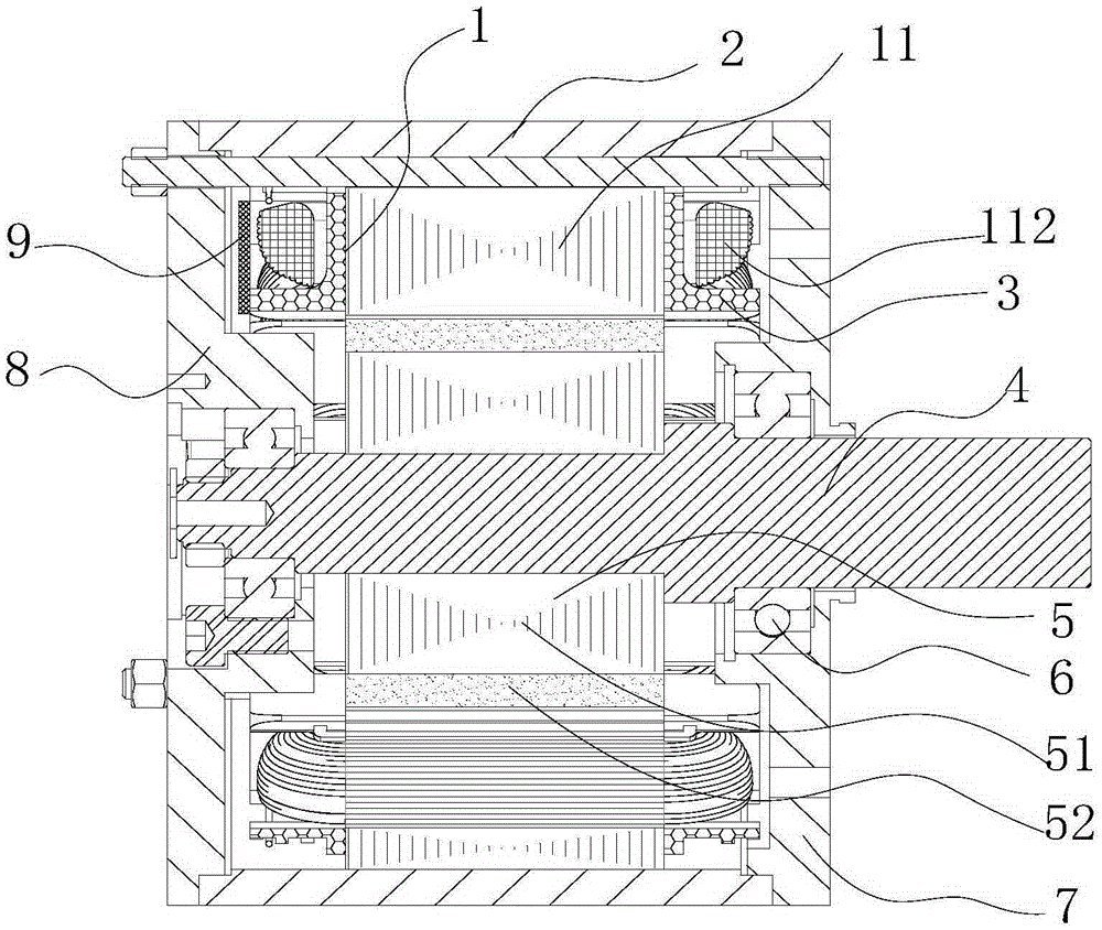
[0034] Such as figure 1As shown, the permanent magnet brushless DC motor for pure electric vehicles of the present invention includes an upper end cover 8, a motor housing 2 and a lower end cover 7 connected as one, and the inside of the motor housing 2 is provided with a stator 1 and a The rotor 5 that is arranged on the motor shaft 4 and the two ends of the motor shaft 4 are provided with bearings 6. The motor shaft 4 is the rotation center of the rotor 5 when it rotates about the stator 1. The bearing 6 is located on the upper end cover 8 and the lower end cover 7. The motor shaft 4 is supported, and the stator 1 includes a stator core 11 with stator slots 111 evenly distributed inside and a winding coil 112 embedded in the stator slot 111. The two ends of the stator core 11 are provided with an insulating frame 3, and the insulating frame 3 is provided with a circuit The plate assembly 9 and the rotor 5 include a rotor core 51 and an even number of permanent magnets 52 uni...
Embodiment 2
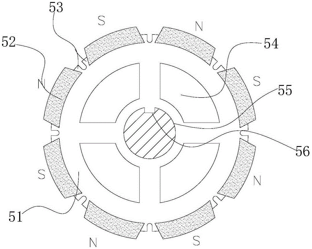
[0039] Such as figure 2 As shown, on the basis of Embodiment 1, the rotor 5 adopts a radial structure. The rotor 5 includes a rotor core 51 and an even number of permanent magnets 52 evenly distributed around it. The permanent magnets 52 are radially magnetized, and the rotor core 51 Dovetail teeth 53 are arranged on the outer circumference of the rotor core 51, and 2p evenly distributed dovetail teeth 53 are arranged on the outer circumference of the rotor iron core 51, where p is the number of pole pairs of the motor, and the permanent magnet 52 is located in the open slot between the two dovetail teeth 53 , that is, each permanent magnet 52 has the same dovetail teeth 53 on both sides, which can fix the permanent magnet 52 in the circumferential and radial directions, which is more reliable and firm than the surface-mounted rotor structure bonded by glue, and is suitable for higher The use environment of the rotating speed, the middle part of the rotor iron core 51 is prov...
Embodiment 3
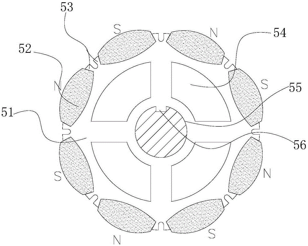
[0041] Such as image 3 As shown, on the basis of Embodiment 1, the rotor 5 adopts a radial structure, and the structure of the rotor 5 is consistent with the description in Embodiment 2. The shape of the permanent magnet 52 is a double-sided protruding shuttle. In the permanent magnet 52 Under the premise of the same length, the thickness of the permanent magnet 52 is increased, which further enhances the anti-demagnetization ability and overload capacity of the permanent magnet 52. At the same time, under the same reverse magnetic field, the permanent magnet 52 can provide higher air gap magnetic dense Br, thereby improving the working point of the permanent magnet 52 of the motor, increasing the overload capacity, and enhancing the anti-demagnetization ability.
PUM
 Abstract
Description
Claims
Application Information