Method and device for forming optical glass

A technology of optical glass and forming device, which is applied in glass forming, glass rolling, glass production, etc. It can solve the problems of large space at the material nozzle, deterioration of glass coloration, and poor molding efficiency. , achieve the effect of shortening the operation time and not easy to shrink the grain

Active Publication Date: 2017-08-04
HUBEI NEW HUAGUANG NEW INFORMATION MATERIALS CO LTD
View PDF4 Cites 0 Cited by
  • Summary
  • Abstract
  • Description
  • Claims
  • Application Information

AI Technical Summary

Problems solved by technology

This operation shortens the pressing interval, but because the glass parts that have been moved out of the pressing position still need to be lifted or vacuumed to be taken out, many actions cannot solve the problem of pressing efficiency well.
However, because the multi-stations of this equipment are distributed along the center of a circle, it takes up a lot of space at the mouth of the material pipe, making it difficult to arrange the production line. At the same time, due to the horizontal rotation mode of production, it is difficult for personnel to access observation and operation.
[0004] When producing small pieces, because the weight of each piece is very small, the above two operation methods must slow down the flow of molten glass in the material pipe, which further affects the production efficiency
The reduction of the discharge volume of the furnace prolongs the residence time of the molten glass in the furnace, and the coloring degree of the glass will become worse; at the same time, due to the reduction of the discharge volume, the material pipe becomes thinner, the flow rate slows down, and the glass is prone to crystallization, which leads to the product being scrapped
At the same time, the longer the molten liquid stays in the furnace, the more energy consumption per unit product will be invisible, and the production cost will be greatly increased.

Method used


Image

  • Method and device for forming optical glass
  • Method and device for forming optical glass

Examples


Embodiment Construction

[0025] The present invention will be further described below in conjunction with the accompanying drawings.

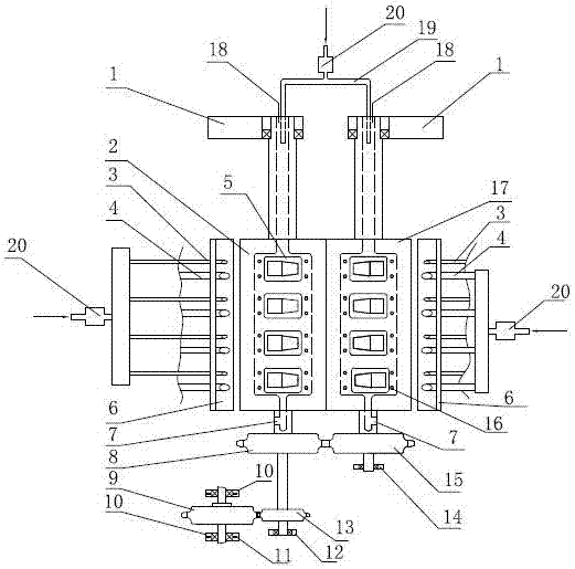
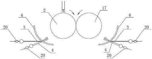
[0026] Such as figure 1 , figure 2 shown. The forming device of the optical glass of the present invention comprises a driving roller 2, a passive roller 17, a driving wheel A9, a driving wheel A13, a driving wheel B8, a driving wheel B15, a first bearing support 1, a second bearing support 10, a third Bearing support 12, fourth bearing support 14, a pair of heating and cooling guide covers 6 and rolling mold 5. The stepped shaft at one end of the driving roller 2 is directly fixed on the first bearing support 1, and the stepped shaft at the other end is fixed on the third bearing support 12 after the driving wheel B8 and the driven wheel A13 are installed. The stepped shaft at one end of the driven roller 17 is fixed on the first bearing support 1, and the stepped shaft at the other end is fixed on the fourth bearing support 14 after the driven wheel B15 is instal...


PUM


Abstract

The title of the present invention is a method and device for forming optical glass. The invention belongs to the technical field of optical glass molding. It mainly solves the problems of low optical glass molding efficiency, low yield rate, complicated molding process and large space occupation. Its main features are: it includes active rollers and passive rollers with the same diameter and fixed horizontally on the bearing support; there are installation grooves on the peripheral surfaces of the active and passive rollers, and rolling molds with different mold cavities can be installed in the grooves. ; Both the active and passive rollers are provided with an axial cavity, one end of the cavity is connected with a cold air pipe, and the other end is provided with a ventilation hole; a driving wheel B with the same diameter and the same number of teeth is installed on the fixed shaft of the active and passive rollers 1. Passive wheel B; heating and cooling guide covers for cold air pipes and gas pipes are fixed on both sides of the main and passive rollers. The invention solves the need for continuous molding of small pieces of optical glass, and can improve the molding quality through monitoring and heating and cooling devices. The rolling device is easy to disassemble and facilitates replacement and maintenance.

Description

technical field [0001] The invention belongs to the technical field of optical glass molding, and in particular relates to a molding device used for manufacturing optical glass products by a roll forming method. Background technique [0002] The traditional production mode of optical glass molded parts is one-time pressing, and the one-time pressing method is vertical pressing up and down. After the pressing is completed, it is necessary to vacuum absorb the molded parts or raise the lower mold until the molded parts are out of the mold cavity and then pulled out by the manipulator. , the process is complicated, and because it cannot be operated continuously, the work efficiency is low. [0003] In order to change a single operation into a continuous operation and improve the molding efficiency, people designed a multi-station press that rotates along a center of circle on this basis. The glass melting furnace liquid drops on a fixed station, and after finishing one molding...

Claims


Application Information

Patent Timeline
Patent Type & Authority Patents(China)
IPC IPC(8): C03B13/01C03B25/00
CPCY02P40/57
Inventor 杨谧玲姜敬陆张小东梁立新徐华峰
Owner HUBEI NEW HUAGUANG NEW INFORMATION MATERIALS CO LTD
Why Eureka
Try Eureka