Multi-cylinder generator

A generator and airframe technology, applied in the direction of electrical components, electromechanical devices, electric components, etc., can solve the problems of large size that cannot be adapted to special occasions, complex and huge power devices, high manufacturing process and high requirements, and achieve the prevention of stress fatigue. The effect of low air tightness requirements and low manufacturing process requirements

Inactive Publication Date: 2016-03-02
GUANGDONG UNIV OF TECH
View PDF5 Cites 0 Cited by
  • Summary
  • Abstract
  • Description
  • Claims
  • Application Information

AI Technical Summary

Problems solved by technology

Both external combustion engines and internal combustion engines will produce exhaust gas due to insufficient combustion, and the combustion efficiency is low. The multi-stage transmission makes the conversion efficiency low, which not only pollutes the environment but also causes waste of resources. They are generally large in size. At the same time, the entire power plant is too complicated and huge , the size is too large to adapt to special occasions, the control response is slow, the manufacturing process and requirements are high, and the manufacturing cost is high. It mainly relies on the energy conversion of fossil fuels, and its irreparable pollution has caused profound impacts on the ecological environment and climate. Repeatedly Persecuted by nature, human beings have to switch to renewable energy instead of non-renewable energy such as fossil fuels. This type of generator consumes a lot of energy and pollutes a lot, causing a waste of resources and causing great harm to the environment; renewable energy is The most reliable energy source, but considering the limitations of the climate environment and production technology, wind power is currently used as a symbol of the development of magnetic energy. The wind blades are used to convert kinetic energy into electrical energy without generating harmful gases. In the control field, permanent energy is used to improve efficiency. Magnets, at present, the generator servo system mostly uses permanent magnet linear generators

Method used


Image

  • Multi-cylinder generator
  • Multi-cylinder generator
  • Multi-cylinder generator

Examples


Embodiment

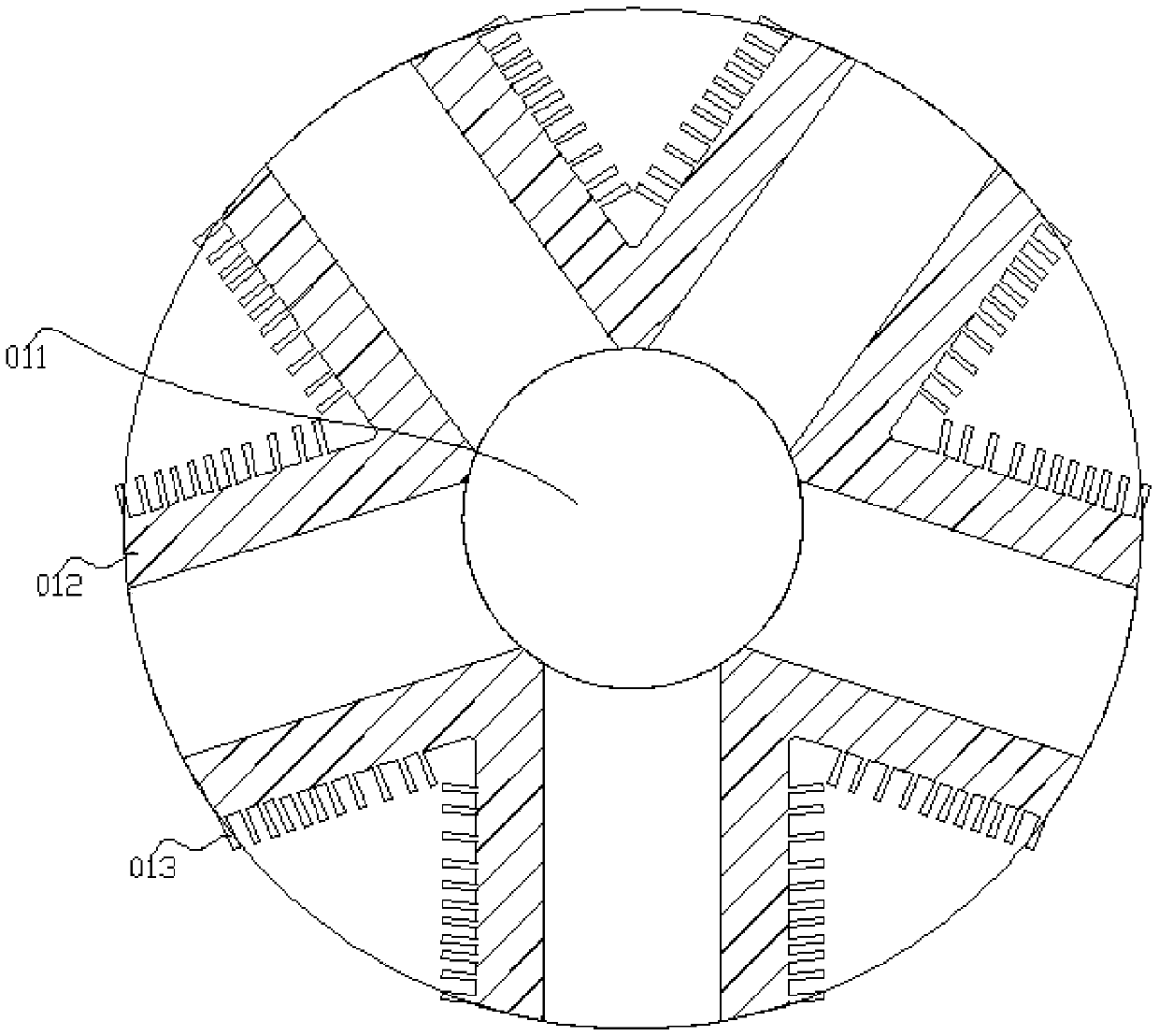
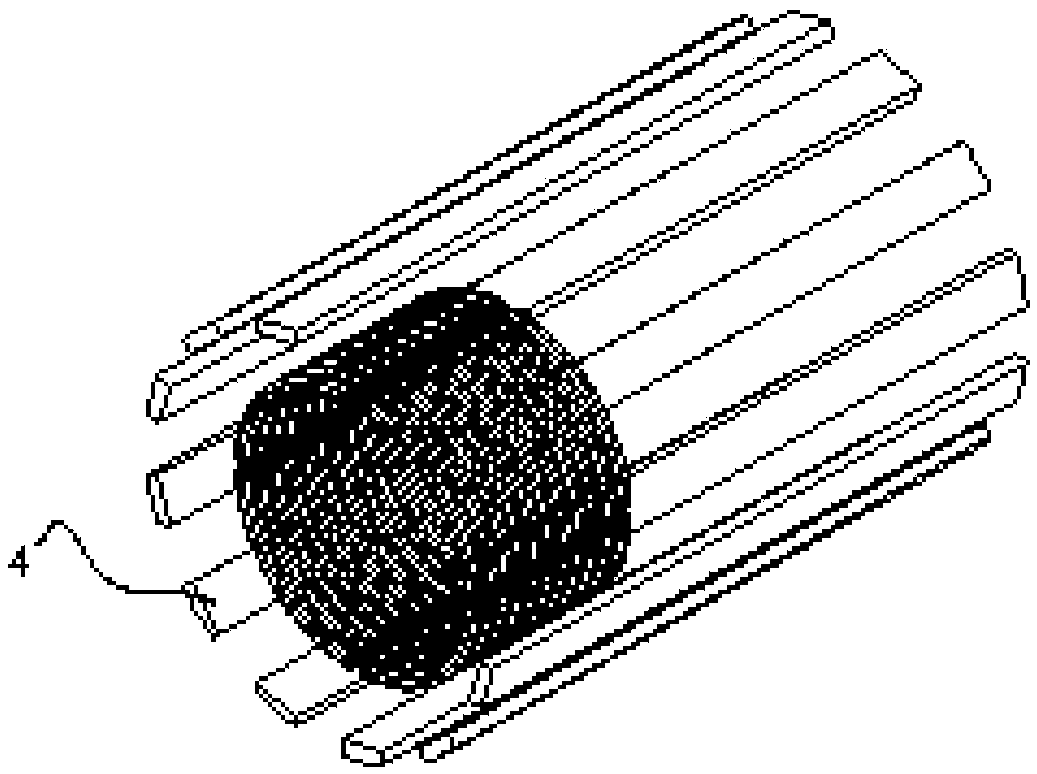
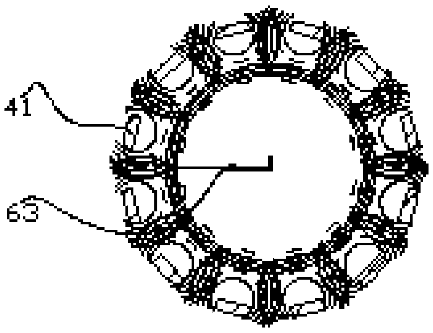
[0028] The structure diagram of the present invention is as figure 1 , 2 , 3, and 4, the multi-cylinder generator of the present invention includes a generator body 1, a moving sleeve 2, a connecting rod 7 and an output shaft 10, and the generator body 1 includes a body 012 and a machine cavity 011, and the body 012 is provided with a machine cavity 011, the movement sleeve 2 is set in the machine cavity 011 provided in the body 012, the permanent magnet group 4 is installed between the body 012 and the movement sleeve 2, and the movement sleeve 2 is equipped with a piston 5, The outer cylindrical surface of the moving sleeve 2 has an interference fit with the permanent magnet group 4, the permanent magnet group 4 has an interference fit with the body 012, the piston 5 has a clearance fit with the inner cylindrical surface of the moving sleeve 2, and the piston 5 and the connecting rod 7 have an interference fit. One end is connected, and the other end of the connecting rod 7...


PUM


Abstract

The invention discloses a multi-cylinder generator, which comprises a generator body, movement sleeves, connecting rods, an output shaft and an eccentric structure, wherein the generator body comprises a machine body and a machine cavity; the movement sleeves are arranged in the machine cavity in the machine body; permanent magnet groups are arranged between the machine body and the movement sleeves; pistons are assembled in the movement sleeves; the outer cylindrical surfaces of the movement sleeves and the permanent magnet groups are in interference fit; the permanent magnet groups and the machine body are in interference fit; the pistons and the inner cylindrical surfaces of the movement sleeves are in interference fit; the pistons are connected with one end of each connecting rod; the other end of each connecting rod is connected with the output shaft; the output shaft is located at the center of the machine body; the rotating center of the eccentric structure is connected with the output shaft; off centers of the eccentric structure are distributed in a circumference array around the center; a coil assembly winds one end of each piston and is fixed on each piston; two ends of each coil of each coil assembly are connected with a coil rectifying circuit through a conducting liquid; the coil assemblies are connected with an external end power supply; and the permanent magnet groups generate uniform magnetic fields of covering the overall coil assemblies. The multi-cylinder generator is simple in structure, low in technological requirements and low in cost.

Description

technical field [0001] The invention is a multi-cylinder generator, which belongs to the innovative technology of the multi-cylinder generator. Background technique [0002] The development of internal combustion engines in the era of the industrial revolution has promoted the rapid development of society. At present, the production volume of generators is large and the sales volume is wide. The form of mechanical energy is converted into electrical energy, mainly including internal combustion engines, external combustion engines, electric motors, etc. Both external combustion engines and internal combustion engines will produce exhaust gas due to insufficient combustion, and the combustion efficiency is low. The multi-stage transmission makes the conversion efficiency low, which not only pollutes the environment but also causes waste of resources. They are generally large in size. At the same time, the entire power plant is too complicated and huge , the size is too large ...

Claims


Application Information

Patent Timeline
Patent Type & Authority Applications(China)
IPC IPC(8): H02K7/075
Inventor 罗良维杨春燕
Owner GUANGDONG UNIV OF TECH
Why Eureka
Try Eureka