Pipe flange welding workstation

A welding workstation, pipe flange technology, applied in welding equipment, auxiliary welding equipment, welding/cutting auxiliary equipment, etc., can solve the problems of high labor intensity, poor welding quality, low welding efficiency, etc. Convenient, long-lasting effect

Inactive Publication Date: 2016-03-09
WUXI SANHONG MACHINERY EQUIP
View PDF8 Cites 7 Cited by
  • Summary
  • Abstract
  • Description
  • Claims
  • Application Information

AI Technical Summary

Problems solved by technology

[0003] The purpose of the present invention is to address the above problems and provide a pipe flange welding workstation to solve the problems of manual welding, high labor intensity, low welding efficiency and poor welding quality in the existing pipe flange welding production mode

Method used


Image

  • Pipe flange welding workstation
  • Pipe flange welding workstation

Examples


Embodiment Construction

[0017] The technical solutions of the present invention will be further described below in conjunction with the accompanying drawings and through specific implementation methods. It should be understood that the embodiments described here are only used to explain the present invention, but not to limit the present invention.

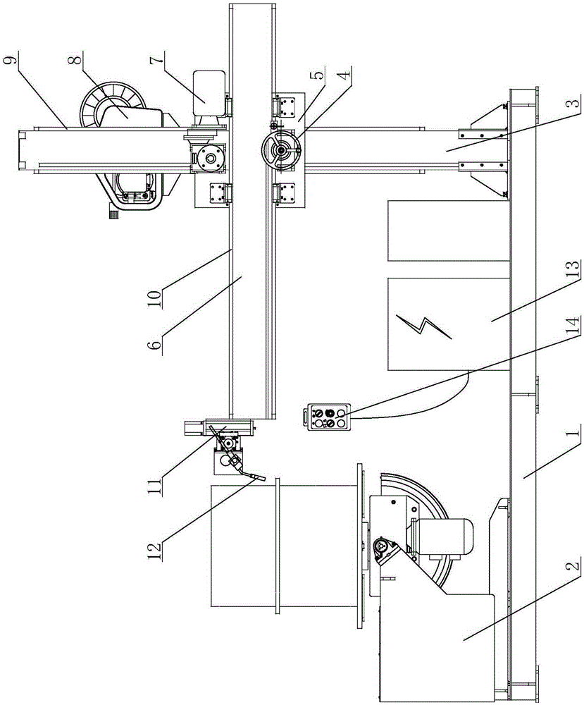
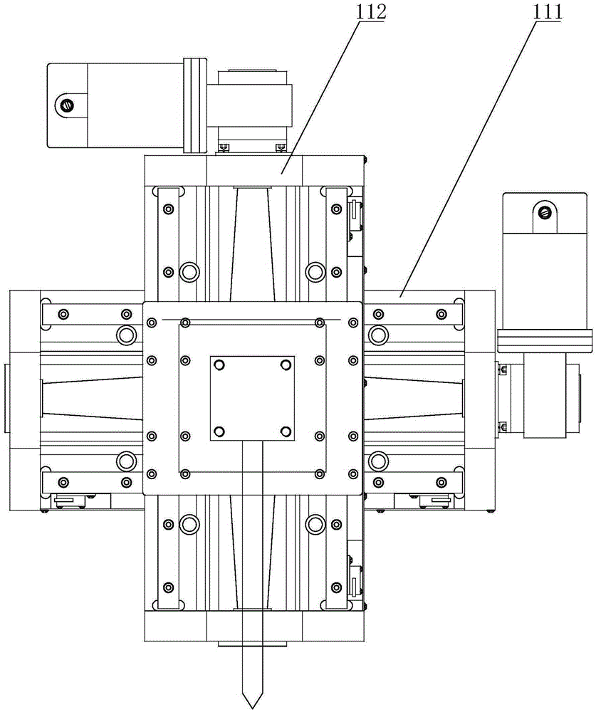
[0018] Please refer to figure 1 and figure 2 as shown, figure 1 It is a structural schematic diagram of a pipe flange welding workstation of the present invention; figure 2 It is a structural schematic diagram of the precision fine-tuning device of the present invention.

[0019] In this embodiment, a pipe flange welding workstation includes a base 1 and a controller 13 installed on the base 1, the controller 13 is electrically connected to a hand control box 14, and the left end of the base 1 is provided with a Positioner 2, the positioner 2 is electrically connected with the controller 13, the positioner 2 is provided with a workbench that can dr...


PUM


Abstract

The invention discloses a pipe flange welding workstation. The pipe flange welding workstation comprises a base, wherein a positioner is arranged on one end of the base; the positioner is electrically connected with a controller; a workbench which can drive a workpiece to rotate or turnover is arranged on the positioner; a stand column which is perpendicularly arranged is arranged at the other end of the base; a wire feeder is mounted on the stand column; the wire feeder is electrically connected with the controller; a lifting base is mounted on the stand column in an up-and-down moving manner; a cross arm is mounted on the lifting base in a horizontal moving manner; a precise micro manipulator is mounted on the end head of one end, which is close to the positioner, of the cross arm; the precise micro manipulator is controlled by the controller; a welding gun is mounted on the precise micro manipulator; the welding gun is electrically connected with the controller. The pipe flange welding workstation disclosed by the invention is simple and compact in structure, flexible and convenient to operate, durable, and convenient and swift to mount and dismantle. According to the pipe flange welding workstation, the production intensity is effectively reduced, the production cost is reduced, and the welding efficiency and the welding quality are improved.

Description

technical field [0001] The invention relates to a welding device, in particular to a pipe flange welding workstation. Background technique [0002] Pipe flanges are widely used in petroleum, chemical, natural gas and other industries. In the production process of the pipe flange, it needs to go through the welding process. At present, various manufacturers mostly use manual welding to produce, first install the workpiece on the simple positioner, and realize manual welding through the rotation of the positioner; The welding method requires the operator to hold the welding torch for a long time, which is not only prone to fatigue, but also has low work efficiency; and the hand-held welding torch is prone to vibration, which affects the quality and appearance of the welding seam; in addition, the positioner and the welding machine have independent operation control systems , the operator needs to face multiple sets of separate control systems during operation, the operability...

Claims


Application Information

Patent Timeline
Patent Type & Authority Applications(China)
IPC IPC(8): B23K37/00B23K37/053B23K37/02
CPCB23K37/00B23K37/0211B23K37/053
Inventor 徐友红
Owner WUXI SANHONG MACHINERY EQUIP
Why Eureka
Try Eureka