
A frozen foundation for transmission towers

A technology for power transmission towers and frozen soil, which is applied in the direction of infrastructure engineering, towers, mechanical vibration attenuation devices, etc., and can solve the problem of the difficulty of completely compacting and restoring the soil layer structure, the influence of the stability of the frozen soil foundation of the tower foundation, and the inability to protect the frozen soil Layer structure and other issues, to achieve good anti-dance effect, improve anti-dance performance, and improve the effect of service life

Active Publication Date: 2018-11-09
CHINA ELECTRIC POWER RES INST +2
View PDF5 Cites 0 Cited by
  • Summary
  • Abstract
  • Description
  • Claims
  • Application Information

AI Technical Summary

Problems solved by technology

[0003] Existing permafrost foundations often use conical column foundations, excavated piles or cast-in-situ piles, which will involve the following problems: ①The pile diameter is large, and the pile foundation is relatively shallow. In summer, the heat from the upper end of the pile foundation and the surrounding surface will be quickly and massively transferred to the frozen soil below through the tower foundation, which will have an important impact on the stability of the frozen soil foundation of the tower foundation
② The structure of the foundation project is complex, and it is difficult to completely compact and restore the original soil layer structure during the construction process
③Complicated structure, high production and maintenance costs
④ The existing prefabricated foundation uses angle steel as the support material, which only has a single supporting force function and cannot protect the permafrost structure
⑤The existing prefabricated foundation only has a single supporting force function, and the stability is poor

Method used


Image

  • A frozen foundation for transmission towers
  • A frozen foundation for transmission towers
  • A frozen foundation for transmission towers

Examples


Embodiment 1

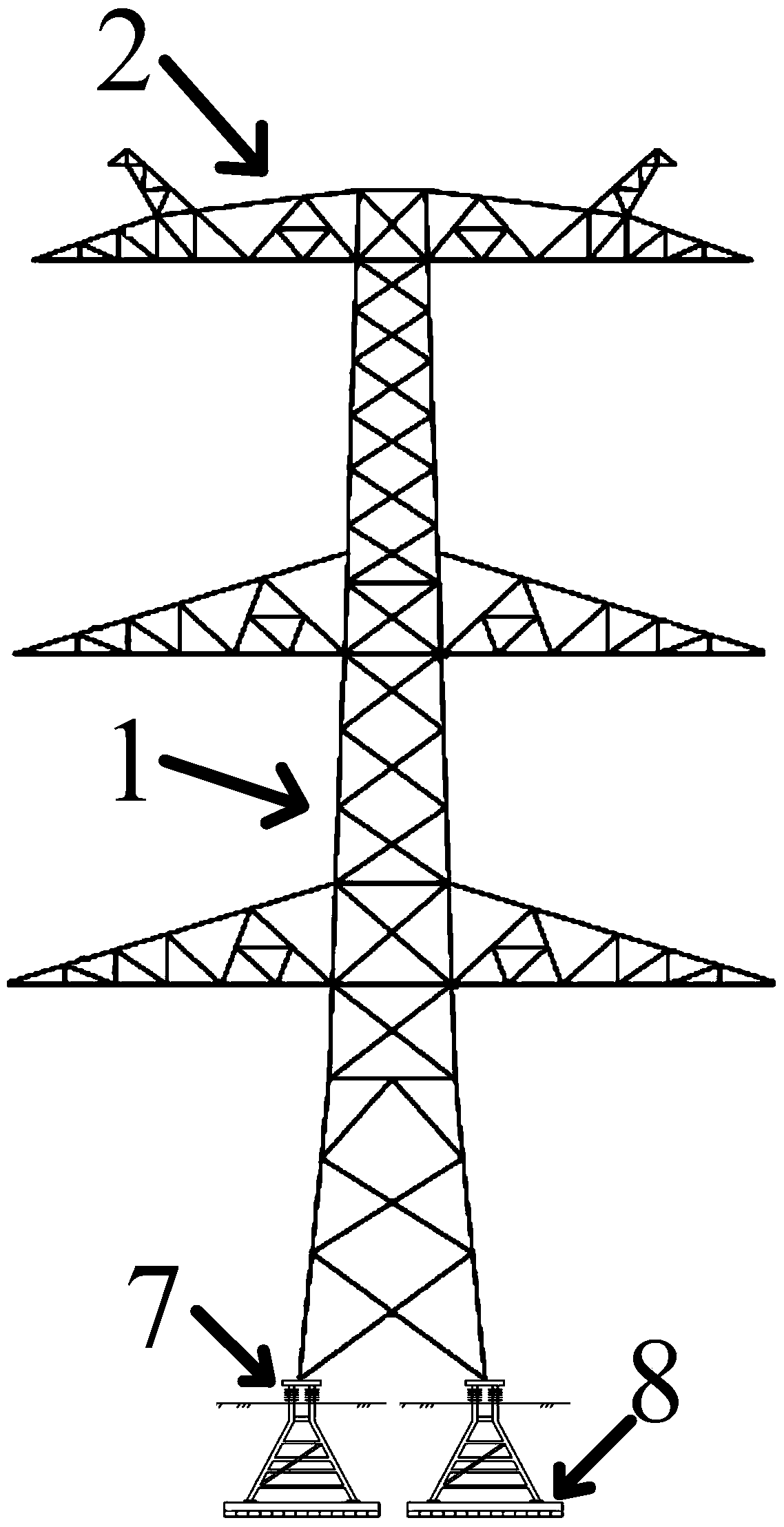
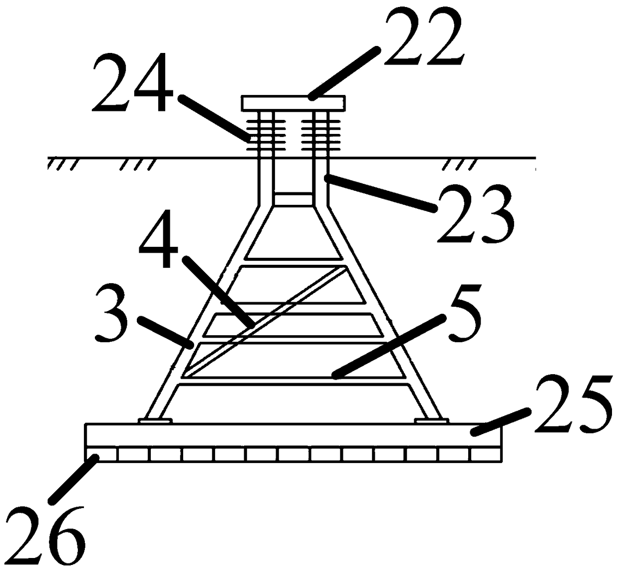
[0051] Such as figure 1 As shown, a frozen soil foundation for a power transmission tower, the power transmission tower is provided with a vertically arranged tower body 1, a tower head 2 arranged horizontally on the upper end of the tower body 1, and a tower head 2 arranged on the tower head 2 The power transmission wire; the frozen soil foundation is provided with a triangular frame formed by the angle steel main material 3, the angle steel oblique material 4 and the horizontally arranged evaporation tubes 5,

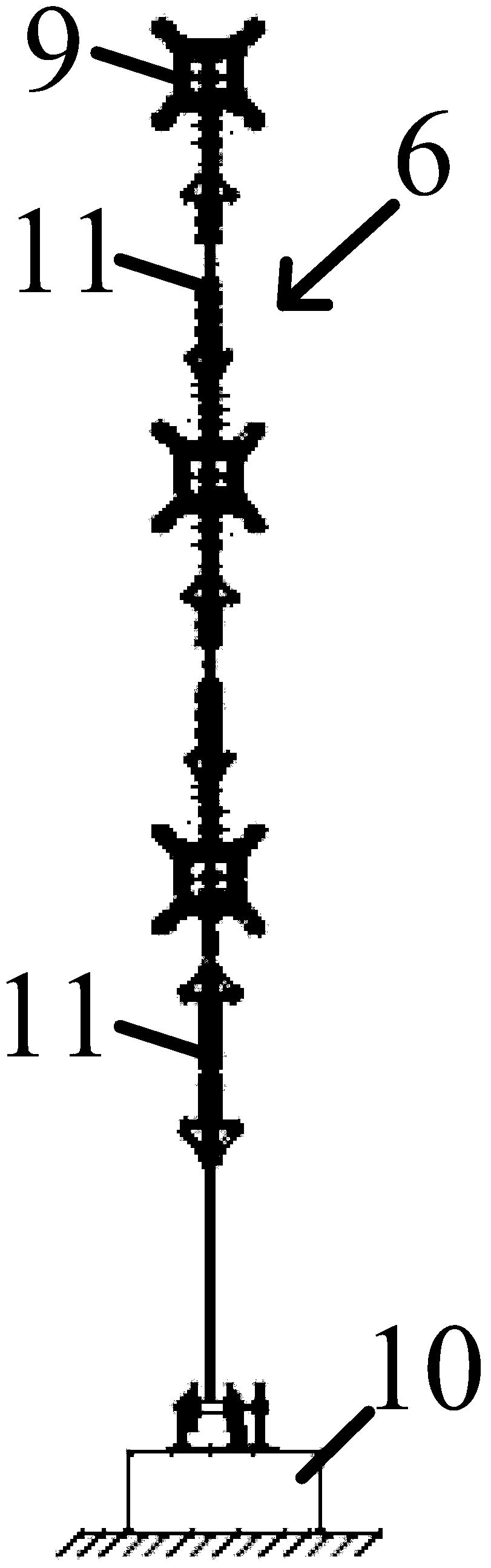
[0052] Such as image 3 As shown, the transmission wire is provided with an anti-dancing device 6,

[0053] Such as figure 1 As shown, the frozen soil foundation is arranged below the frozen soil surface, and its upper and lower ends are respectively provided with a tower foot connecting seat 7 connected with the tower foot and a foundation fixing seat 8 for fixing the frozen soil foundation.

[0054] Such as image 3 As shown, the anti-dancing device 6 is provided ...


PUM

PropertyMeasurementUnit
particle sizeaaaaaaaaaa

Abstract

The invention relates to a frozen earth foundation for a power transmission tower. The power transmission tower comprises a vertically-arranged tower body, a tower head transversely arranged at the upper end of the tower body and a power transmission line arranged on the tower head. The frozen earth foundation comprises a triangular frame formed by connecting angle iron principal materials, an angle iron diagonal member and horizontally-arranged evaporation pipes in a cross manner. The power transmission line is provided with an anti-galloping device. The frozen earth foundation is arranged below the frozen earth ground surface, tower leg connecting bases connected with tower legs are arranged at the upper end of the frozen earth foundation, and foundation fixing bases fixing the frozen earth foundation are arranged at the lower end of the frozen earth foundation. According to the frozen earth foundation for the power transmission tower, frozen earth thawing is prevented, the stability of the power transmission tower is enhanced, and production and maintenance cost is reduced.

Description

technical field [0001] The invention relates to cryogenic technology processing equipment, in particular to a frozen soil foundation for power transmission towers. Background technique [0002] Frozen soil is a kind of soil and rock with a temperature lower than 0°C and contains ice. According to the length of frozen soil preservation time, it is mainly divided into seasonal frozen soil (half a month to several months) and permafrost (more than one year). my country's Qinghai-Tibet Plateau is the most widely distributed area of ​​high-altitude and low-latitude permafrost in the world. Not only because of the existence of ice, the properties of permafrost will undergo complex and fundamental changes compared with thawing soil. Once permafrost is disturbed and melted for a long time, its bearing capacity will be greatly reduced, which will bring hidden dangers to engineering safety. In order to prevent permafrost from melting, a permafrost foundation for transmission towers i...

Claims


Application Information

Patent Timeline
Patent Type & Authority Patents(China)
IPC IPC(8): E02D27/42E02D27/35E04H12/00E04H12/10E04H12/24E04H12/22H02G7/14C04B28/02
CPCC04B28/02E02D27/35E02D27/42E02D2300/002E02D2300/0021E04H12/00E04H12/10E04H12/2215E04H12/24H02G7/14C04B18/12C04B18/08C04B18/146C04B14/06C04B14/02C04B24/226C04B2103/60C04B2103/302C04B2103/58
Inventor 毛卫南鲁先龙郑卫锋崔强陈培满银杨文智
Owner CHINA ELECTRIC POWER RES INST
Features
  • Generate Ideas
  • Intellectual Property
  • Life Sciences
  • Materials
  • Tech Scout
  • Unparalleled Data Quality
  • Higher Quality Content
  • 60% Fewer Hallucinations
Learn More