Fluorescence detection instrument and system based on micro-fluidic chip

A microfluidic chip and fluorescence detection technology, applied in the direction of instruments, fluorescence/phosphorescence, analytical materials, etc., can solve the problems of not taking into account volume, resolution and sensitivity, and can not meet the requirements, so as to achieve low processing and manufacturing costs and easy detection , The effect of simple system design

Inactive Publication Date: 2016-03-09
THE NAT CENT FOR NANOSCI & TECH NCNST OF CHINA
9 Cites 6 Cited by

AI-Extracted Technical Summary

Problems solved by technology

[0006] However, the current microfluidic chip fluorescence detection devices for immunoassays cannot take into account the volume, resolution a...

Method used

[0034] Fig. 2 is a schematic diagram of the optical path of a fluorescence detection system based on a microfluidic chip. The microfluidic chip support structure 7 is pulled out, the microfluidic chip 11 is placed on the microfluidic chip support structure chip tray 7, and pushed into the microfluidic chip support structure 7 to avoid the influence of external light; the fluorescence of the m...

Abstract

The invention provides a fluorescence detection instrument and system based on a micro-fluidic chip. The instrument comprises an instrument frame, a light source, a micro-fluidic chip supporting structure, a fluorescence collection module, a light path fixing module and a fluorescence detection module, wherein the light source, the micro-fluidic chip supporting structure, the fluorescence collection module, the light path fixing module and the fluorescence detection module are installed on the instrument frame, the light source is used for stimulating a fluorescent substance on the chip to emit fluorescent light, the micro-fluidic chip supporting structure is used for supporting and moving the chip, and the fluorescence collection module is used for filtering, collecting and focusing a fluorescence signal on the micro-fluidic chip onto the fluorescence detection module; the light path fixing module is used for fixing the position of the fluorescence collection module and for light path adjustment, and the fluorescence detection module is used for converting a received optical signal into an analog electrical signal and then converting the analog electrical signal into a digital electrical signal. The instrument is connected with a computer to form a system. The instrument can meet the requirement for fluorescence detection on the micro-fluidic chip. The instrument is high in resolution ratio and sensitivity, simple and compact in structure, small in size, and convenient to carry and use.

Application Domain

Technology Topic

Image

  • Fluorescence detection instrument and system based on micro-fluidic chip
  • Fluorescence detection instrument and system based on micro-fluidic chip
  • Fluorescence detection instrument and system based on micro-fluidic chip

Examples

  • Experimental program(1)

Example Embodiment

[0035] Example 1
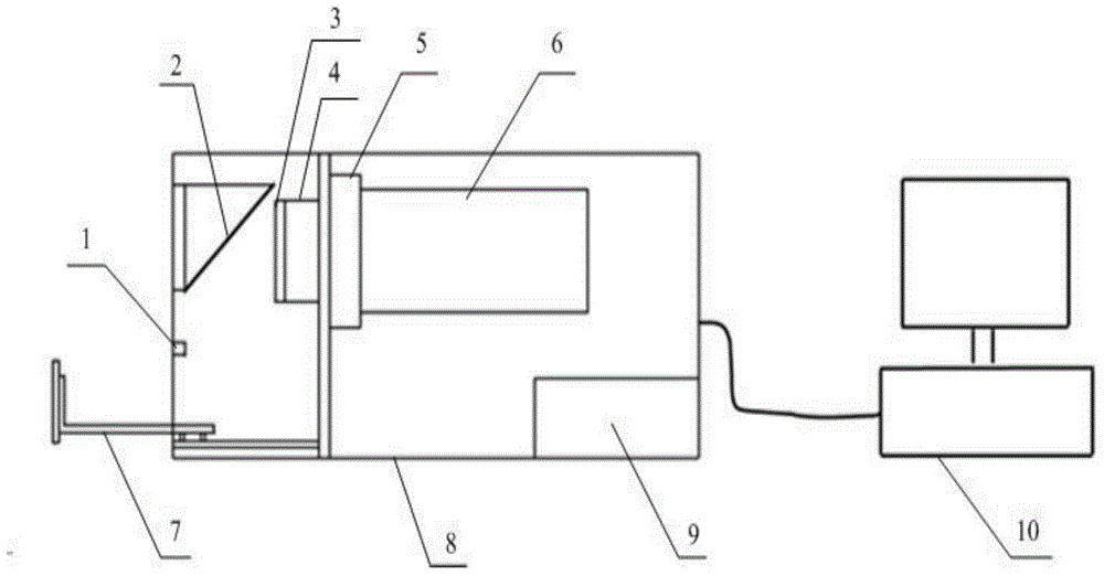
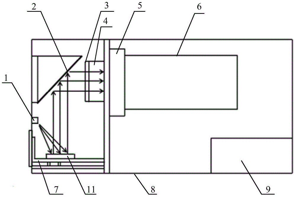
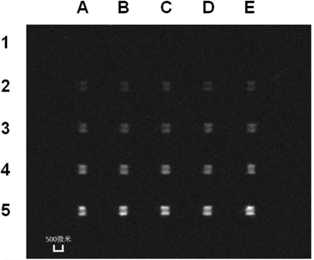
[0036] The functional layer of the microfluidic chip 11 selected in this embodiment is mainly composed of a cuboid channel and a conical inlet, the channel width is 500 microns, and the height is 500 microns. The optical filter 3 selected in this embodiment is the FF-05 optical filter in the center of the Daheng Optical Film; the fluorescent substance on the microfluidic chip 11 is FITC, its molecular weight is 389.4, and its maximum absorption wavelength is 490-495nm. The emitted light wavelength is 525-530nm; the selected light source 1 is an LED light source; the selected fluorescence detection module 6 is a CCD camera; the selected microfluidic chip support structure 7 is a chip tray. Cover the longitudinal microfluidic pipeline on the substrate of the microfluidic chip 11, pass through the A/B/C/D/E pipelines into the AFP (alpha-fetoantigen) capture antibody, suck it out after 30 minutes, and remove the vertical microfluidic pipeline; Cover the horizontal microfluidic pipeline, after the pipeline is sealed by bovine serum albumin solution, add AFP antigen 0ng/mL, 20ng/mL, 40ng/mL, 80ng/mL, 160ng to the 1/2/3/4/5 pipeline in sequence /mL, after incubating for 30 minutes, add the cleaning solution, FITC-labeled AFP detection antibody, and cleaning solution in sequence; place the microfluidic chip 11 on the chip tray of the instrument, push the tray to the designated position, and turn on the detection and analysis function of the instrument Software, read the fluorescent signal, the test results are as follows image 3 shown. It can be seen from the figure that as the concentration of AFP antigen increases, the intensity of the fluorescent signal increases gradually.

PUM

no PUM

Description & Claims & Application Information

We can also present the details of the Description, Claims and Application information to help users get a comprehensive understanding of the technical details of the patent, such as background art, summary of invention, brief description of drawings, description of embodiments, and other original content. On the other hand, users can also determine the specific scope of protection of the technology through the list of claims; as well as understand the changes in the life cycle of the technology with the presentation of the patent timeline. Login to view more.

Similar technology patents

Fluid channel, motor with same and solid-liquid separation system

ActiveCN107159319ASmooth passageEasy to put in and take outFluid transfer labwareFluid controllersMotor shaftStator
Owner:唐凌霄

Teaching material storage device

InactiveCN113023062AConvenient overall organizationEasy to put in and take outExternal framesContainers to prevent mechanical damageStructural engineeringMaterial storage
Owner:WENZHOU POLYTECHNIC

Carton

InactiveCN102730263ANot easy to shakeEasy to put in and take outRigid containersFistEngineering
Owner:PEGATRON

Classification and recommendation of technical efficacy words

  • Easy to put in and take out

Distillatory kettle for plant sesame oil

ActiveCN104606909ASimple structureEasy to put in and take outDistillation in boilers/stillsEssential-oils/perfumesWater tanksHeat energy
Owner:GUANGXI BONENG BIOMASS ENERGY TECH CO LTD

Rotary tower type non-stop unwinding equipment

ActiveCN111532846AImprove efficiencyEasy to put in and take outWebs handlingWall plateIndustrial engineering
Owner:青州蒙特机械有限公司
Why Eureka
Try Eureka