
Nondestructive Separation Method and Separation Subsystem for Arbitrarily Multiplexed Orbital Angular Momentum States

An orbital angular momentum and separation system technology, applied in the field of optics and wireless communication, can solve the problems of no specific solution for separation topological charge, destruction of OAM state space structure, complex implementation structure, etc., to achieve good compatibility and applicability, Ease of manufacture, flexible composition of effects

Active Publication Date: 2019-01-11
NANJING UNIV OF POSTS & TELECOMM
View PDF2 Cites 0 Cited by
  • Summary
  • Abstract
  • Description
  • Claims
  • Application Information

AI Technical Summary

Problems solved by technology

However, when using this method to separate more OAM states, the system structure will be very complicated, and the realization of the Mach-Zehnder interference process is more complicated
In 2010, Martin P.J.Lavery et al. proposed a new method for efficiently separating OAM states. Based on the principle of static optics, the coordinate transformation is used to convert the spiral phase beam into a transverse phase gradient light, and then through the lens to separate each OAM state. The light of the state can be focused to different lateral positions to distinguish different OAM states, but the implementation still requires the use of expensive equipment—spatial light modulator, and the spatial structure of the OAM state will be destroyed after the separation is completed.
In 2014, Lixiang Chen et al. proposed a method for separating orbital angular momentum states based on the polarization properties of light. The implementation structure of this method is still relatively complicated, and it does not give the separation of multiplexed OAM states with opposite topological charges (ie, +l and -l multiplexed OAM state) specific scheme

Method used


Image

  • Nondestructive Separation Method and Separation Subsystem for Arbitrarily Multiplexed Orbital Angular Momentum States
  • Nondestructive Separation Method and Separation Subsystem for Arbitrarily Multiplexed Orbital Angular Momentum States
  • Nondestructive Separation Method and Separation Subsystem for Arbitrarily Multiplexed Orbital Angular Momentum States

Examples


Embodiment 1

[0039] The invention provides a method for nondestructively separating arbitrary multiplexed orbital angular momentum states, the method comprising the following steps:

[0040] Step 1: Generate a beam of multiplexed orbital angular momentum states, wherein n positive l-value orbital angular momentum states are generated by horizontally polarized light, and m negative l-value orbital angular momentum states are generated by vertically polarized light;

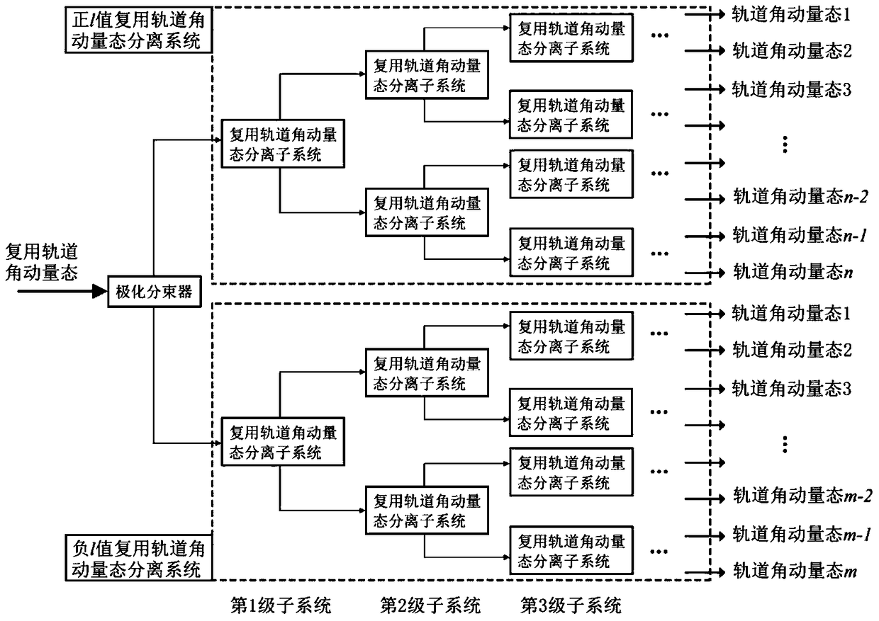
[0041] Step 2: If figure 1 As shown, the incident multiplexed orbital angular momentum state beam is split into two paths through a polarization beam splitter, in which the horizontally polarized light enters the positive l-value multiplexed orbital angular momentum state separation system, and the vertically polarized light enters the negative l-value Multiplexing orbital angular momentum state separation system. These two systems are mutually independent cascade systems, respectively realizing the separation of the positive l-...

Embodiment 2

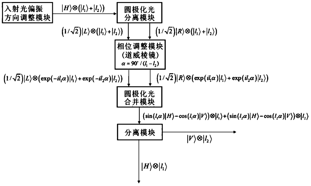
[0046] The invention provides a multiplexing orbital angular momentum state separation subsystem, which is the basic structure for realizing the method of non-destructive separation of arbitrary multiplexing orbital angular momentum state. Each multiplexing orbital angle momentum state separation subsystem includes: incident light polarization direction adjustment module, circular polarization light separation module, phase adjustment module, circular polarization light combination module and separation module, and its work flow chart is as follows figure 2 shown.

[0047] The function of the incident light polarization direction adjustment module is to adjust the incident linearly polarized light into horizontally polarized light.

[0048] The function of the circularly polarized light separation module is to realize the separation of the left circularly polarized component and the right circularly polarized component in the horizontally polarized light, namely

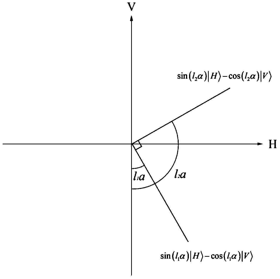
[0049] T...

Embodiment 3

[0054] Assuming that n positive l-value orbital angular momentum states in a beam of multiplexed orbital angular momentum states are generated by horizontally polarized light, and m negative l-value orbital angular momentum states are generated by vertically polarized light, then the multiplexed state can be Recorded as:

[0055]

[0056] Utilize the concrete separation steps of the inventive method as follows:

[0057] Step 1: first let the multiplexed orbital angular momentum state beams enter a polarization beam splitter ( Figure 5 denoted as PBS 0), then the passing beam is The reflected beam is After that, the two beams respectively pass through two cascaded separation systems, that is, a positive l-value multiplexed orbital angular momentum state separation system and a negative l-value multiplexed orbital angular momentum state separation system. (The following steps are illustrated by taking the positive l value multiplexing orbital angular momentum state sepa...


PUM


Abstract

The invention discloses a non-damage separating method and separating subsystems of random multiplex rail angular momentum states. By the aid of the light polarization property, the non-damage separation of random multiplex rail angular momentum states is achieved by cascading the multiple multiplex rail angular momentum state separating subsystems. For each subsystem, each rail angular momentum state in the input multiplex states can be projected to two horizontal or perpendicular polarity directions according to phase characteristics of itself after being subjected to a series of polarization operation. By cascading n layers of multiplex rail angular momentum state separation subsystems, non-damage separation of 2n rail angular momentum state multiple light beams can be achieved. By means of the separation method, on one hand, a good separation effect is achieved, no damage can be caused to the space structure of rail angular momentum states; on the other hand, optical devices required in the separation process are not complex, are easy to manufacture and have good compatibility and applicability for the existing optical communication technology.

Description

technical field [0001] The invention relates to a method for non-destructive separation of arbitrary multiplexed orbital angular momentum states, which belongs to the technical field of optics and wireless communication. Background technique [0002] Photon is an important carrier of information transmission, and the energy, linear momentum and polarization state of photon can be used as degrees of freedom to carry information. Like other degrees of freedom, the angular momentum of photon has also been proved to be a new type of information carrier in recent years. Angular momentum is divided into two types: spin angular momentum (English name is spin angular momentum, abbreviated as SAM) and orbital angular momentum (English name is orbit angular momentum, abbreviated as OAM), in which spin angular momentum is related to the polarization of photons , which is related to polarization; while the orbital angular momentum is related to the spatial distribution of photons. In ...

Claims


Application Information

Patent Timeline
Patent Type & Authority Patents(China)
IPC IPC(8): G02F1/01
CPCG02F1/0136
Inventor 赵生妹顾晓凡
Owner NANJING UNIV OF POSTS & TELECOMM
Learn More