Block-based switched reluctance motor with short end part and short magnetic circuit and control circuit thereof

A technology of switched reluctance motor and control circuit, applied in the direction of magnetic circuit shape/style/structure, magnetic circuit, magnetic circuit rotating parts, etc. The problems such as the length of the pass loop can achieve the effects of small torque ripple, low control cost, and increased air gap magnetic field width.

Inactive Publication Date: 2016-03-09
SHANDONG UNIV
View PDF7 Cites 9 Cited by
  • Summary
  • Abstract
  • Description
  • Claims
  • Application Information

AI Technical Summary

Problems solved by technology

The internal magnetic flux circuit of the motor with this structure is long, the iron loss and eddy current loss are relatively large, and the paths of the magnetic flux circuits of each winding overlap with each other, resulting in a large impact on the magnetic circuit of the motor when the stator or rotor breaks, and poor fault tolerance; At high speed, due to the tooth pole structure of the rotor, the wind resistance of the rotor is large, and the loss of the motor increases
The existing segmented switched reluctance motors cannot simultaneously solve the problems of large motor pulsation, long winding ends and long magnetic paths under the condition of high winding utilization
Conventional switched reluctance motors adopt an asymmetrical half-bridge circuit structure, and each phase requires two control switch tubes and two freewheeling diodes, and the average control cost per phase of the motor is relatively high

Method used


Image

  • Block-based switched reluctance motor with short end part and short magnetic circuit and control circuit thereof
  • Block-based switched reluctance motor with short end part and short magnetic circuit and control circuit thereof
  • Block-based switched reluctance motor with short end part and short magnetic circuit and control circuit thereof

Examples


Embodiment Construction

[0043] The present invention will be further described below in conjunction with the accompanying drawings and embodiments.

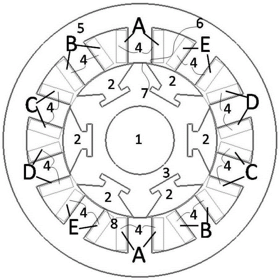
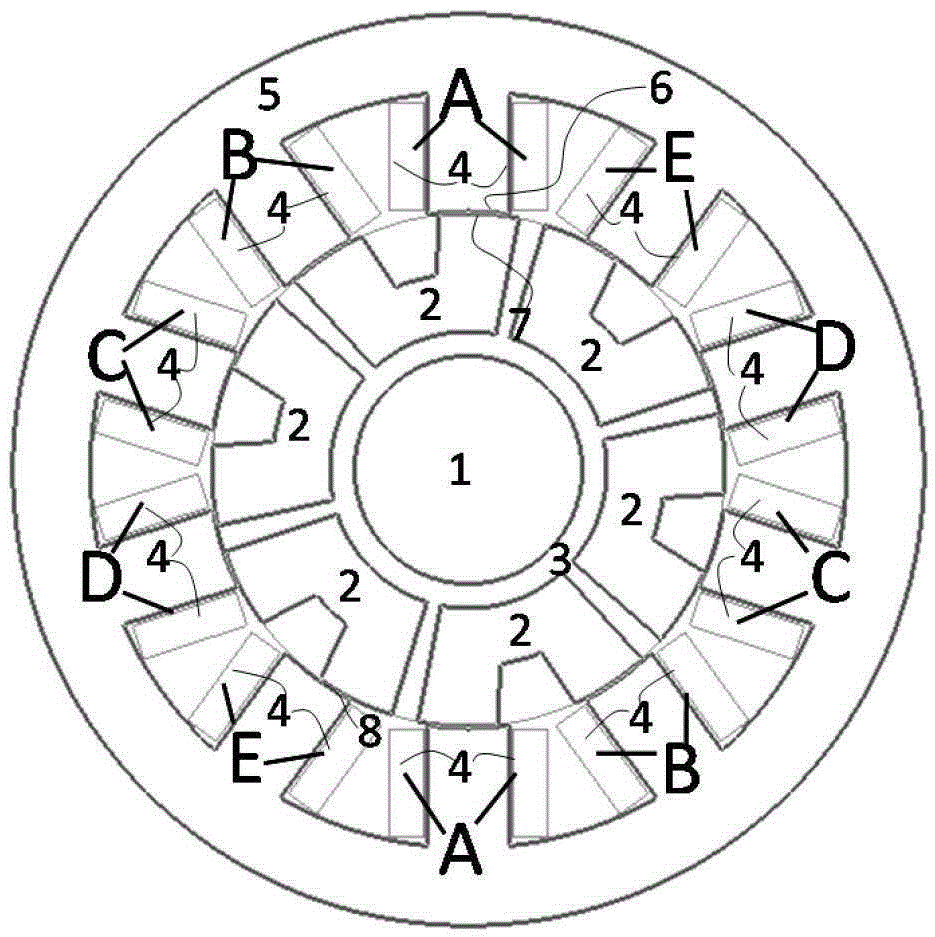
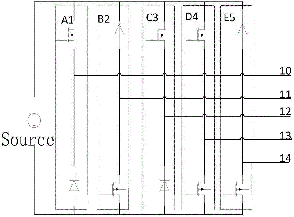
[0044] The segmented switched reluctance motor with short end and short magnetic circuit is a multi-phase motor. The number of stator poles of the motor is even, the number of motor phases is M, and the number of motor stator poles is N. The relationship between the number of motor phases and the number of stator poles is : N=K×M; K=2, 3, 4, 5, 6.... The number of motor phases M≥5 and is an odd number. The number of rotor block-type magnetic materials is the number of rotor poles A control main circuit of short-end short magnetic circuit block type switched reluctance motor includes several bridge arms, the bridge arms are composed of two controllable switching devices or diode devices connected in series, and the bridge arms are directly connected to the power bus Or on the DC bus, the relationship between the number W of bridge arms of the motor con...


PUM


Abstract

The invention discloses a block-based switched reluctance motor with a short end part and a short magnetic circuit and a control circuit thereof. The motor comprises a motor stator and a block-based motor rotor; the stator comprises a stator core and a winding; a rotor part comprises rotor overlaid cores and a non magnetic framework; a plurality of stator teeth are uniformly distributed on the stator core; the stator winding is of a concentrated winding structure and wound on the stator teeth; the rotor overlaid cores are uniformly distributed at the inner side of the stator teeth and embedded in the non magnetic framework; a rotating shaft is arranged at the center of the non magnetic framework; during the running process of the motor, the motor at least has two electrified phases which are adjacent to each other; the route of the magnetic field inside the motor comprises the stator teeth of the two adjacent phases, as well as a stator yoke part, the rotor overlaid core and an air gap between the stator teeth of the two adjacent phases. When the motor disclosed by the invention runs, two adjacent phases are powered on and off at the same time, the width of the air gap magnetic field of the more is improved, the output torque of the motor is improved, and the force density of the motor is increased.

Description

technical field [0001] The invention relates to a block-type switched reluctance motor with short ends and short magnetic circuits and its control circuit. Background technique [0002] The switched reluctance motor follows the principle that the magnetic flux always closes along the path with the largest permeance, and the electromagnetic torque with reluctance properties is generated by the magnetic pull. Switched reluctance motors are simple and robust in construction. The stator coil is easy to embed, the end is firm, most of the heat loss is in the stator, and it is easy to cool; the rotor has no permanent magnet, which can have a higher maximum allowable temperature rise, no winding on the rotor, low cost, and the motor can rotate at high speed without Cause deformation, the moment of inertia of the rotor is small, easy to accelerate and decelerate; the winding current can continue to flow through the freewheeling diode, and feed back the electric energy to the power ...

Claims


Application Information

Patent Timeline
IPC IPC(8): H02K19/10H02K1/14H02K1/24
CPCH02K1/146H02K1/246H02K19/10
Inventor 徐衍亮付东山
Owner SHANDONG UNIV
Why Eureka
Try Eureka