Zero-input current ripple high-gain converter based on double coupling inductors and single switch

A technology of current ripple and coupled inductance, applied in the field of zero-input current ripple high-gain converters, can solve problems such as low efficiency, achieve the effects of increasing voltage gain, improving converter efficiency, and reducing volume and weight

Inactive Publication Date: 2016-03-09
CHINA UNIV OF MINING & TECH
View PDF8 Cites 18 Cited by
  • Summary
  • Abstract
  • Description
  • Claims
  • Application Information

AI Technical Summary

Problems solved by technology

It realizes the high voltage gain of the converter through the voltage doubling function of switching inductors and capacitors, but there is no recovery circuit for leakage inductance energy, and the efficiency is relatively low

Method used


Image

  • Zero-input current ripple high-gain converter based on double coupling inductors and single switch
  • Zero-input current ripple high-gain converter based on double coupling inductors and single switch
  • Zero-input current ripple high-gain converter based on double coupling inductors and single switch

Examples


Embodiment Construction

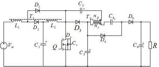
[0037] Such as figure 1 As shown, the zero-input current ripple high-gain converter based on double-coupled inductors and a single switch is characterized in that it includes a DC input power supply (V in ), by the first winding (L 1 ) and the second winding (L 2 ) composed of coupled inductors (T 1 ), the first freewheeling diode (D 1 ), the second freewheeling diode (D 2 ), the energy storage capacitor (C 1 ), controllable power switch tube (Q), clamping diode (D 3 ), by the primary winding (n p ) and the secondary winding (n s ) composed of coupled inductors (T 2 ), the first voltage doubler energy storage capacitor (C 2 ), the second voltage doubler energy storage capacitor (C 3 ), the third voltage doubler energy storage capacitor (C 4 ), the third freewheeling diode (D 4 ), the output diode (D 0 ), the output capacitance (C 0 ), the output load.

[0038] The DC input power supply (V in ) positive pole and coupled inductor (T 1 ) The first winding is conn...


PUM


Abstract

The invention discloses a zero-input current ripple high-gain converter based on double coupling inductors and a single switch. The converter includes a direct current input power supply Vin, coupling inductors T1 and T2, freewheel diodes D1, D2 and D4, an energy storage capacitor C1, a power switch tube Q, a clamping diode D3, voltage-multiplying energy storage capacitors C2, C3 and C4, an output diode D0 and an output capacitor C0. The converter can obtain a high gain of voltage by means of the coupling inductors, the gain is controlled by a duty ratio and a coupling inductance turn ratio and is wide in adjustable range, and voltage and current stress of the switch tube is small; through coupling of an input inductor and an energy storage inductor, and reasonable configuration of a coupling coefficient, input current zero ripples can be realized; a lossless absorption circuit formed by the clamping diode and the energy storage capacitor can reduce voltage spikes of the switch tube; and the freewheel diodes, the voltage-multiplying energy storage capacitors and secondary sides of the coupling inductors form an energy recovery circuit, so that leakage inductance energy is finally fed back to a load side, thereby improving the efficiency of the converter.

Description

technical field [0001] The invention relates to a DC-DC converter in the field of power electronics, in particular to a zero-input current ripple high-gain converter based on double coupled inductors and a single switch. Background technique [0002] Boost converters are widely used in many industrial fields, such as photovoltaic power generation systems, battery energy management systems, PFC circuits, and UPSs. Traditional boost converters have the disadvantages of low boost gain, large switch tube voltage stress, and reverse recovery of diodes. Disadvantages such as large current. In recent years, high-gain converters have become a research hotspot in the field of power electronics, and many achievements have been made. The voltage gain of the coupled inductor boost converter is high, the voltage stress of the switch tube is greatly reduced compared with the traditional converter, the reverse recovery current of the diode is reduced, and the converter has a smaller volum...

Claims


Application Information

Patent Timeline
Patent Type & Authority Applications(China)
IPC IPC(8): H02M1/14H02M3/335
CPCH02M1/143H02M3/33523
Inventor 于东升杨杰王龙朱虹侯圣
Owner CHINA UNIV OF MINING & TECH
Why Eureka
Try Eureka