Device and process for utilizing waste heat of waste flue gas of hot-blast stove

A waste flue gas and hot blast stove technology, which is applied in lighting and heating equipment, furnaces, waste heat treatment, etc., can solve problems such as poor sealing, easy leakage, and equipment damage

Inactive Publication Date: 2016-03-16
SHANDONG DAIRONG ENERGY SAVING ENVIRONMENTAL PROTECTION TECH
View PDF6 Cites 3 Cited by
  • Summary
  • Abstract
  • Description
  • Claims
  • Application Information

AI Technical Summary

Problems solved by technology

[0002] At present, for the utilization of waste flue gas from hot blast stoves, the relatively common method adopted is to use heat pipe heat exchangers, tube heat exchangers, plate heat exchangers, and rotary heat exchangers to recover waste heat. The process of the furnace is to alternately supply air to the furnace, so the demand for preheating and the supply of waste heat will change repeatedly at regular intervals. One hot blast furnace is supplying air, and the other two or three furnaces are firing, and vice versa. , the exhaust gas produced in this way will have periodic changes in both temperature and quantity, which requires relatively high equipment and needs to adapt to changes in temperature and flow. Traditional heat pipe heat exchangers are usually integral heat exchangers , using the heat pipe as the heat transfer element, the area of ​​the heat exchanger is designed according to the design conditions. Under the condition of low temperature or small flow, the temperature of the end tube wall of the heat exchanger is lower than the dew point corrosion due to the non-adjustable heat exchange area. temperature, thus causing damage to the equipment; the tubular heat exchanger performs heat exchange in the way that the flue gas goes through the tube side, and the cold side medium goes through the shell side. The heat area cannot be adjusted, and corrosi...

Method used


Image

  • Device and process for utilizing waste heat of waste flue gas of hot-blast stove

Examples


Embodiment Construction

[0009] In order to enable those skilled in the art to better understand the technical solutions in the present application, the technical solutions in the embodiments of the present application will be clearly and completely described below in conjunction with the drawings in the embodiments of the present application.

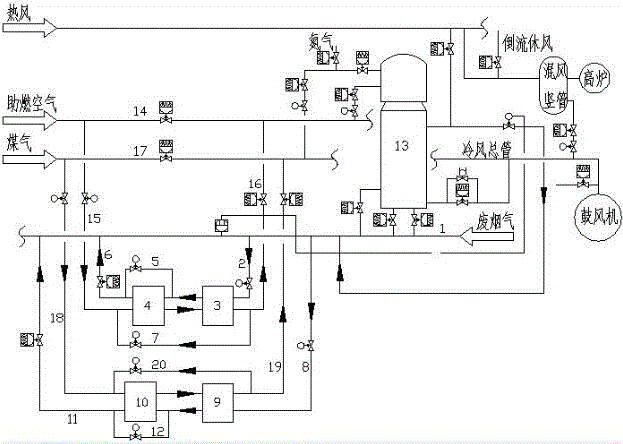
[0010] In this embodiment, the cold medium is air and gas, and the flue gas pipeline is connected with two sets of heat exchangers to preheat the air and gas at the same time. The flue gas pipe 2 in front of the heat exchanger and the pipe 8 in front of the gas heat exchanger enter the secondary air heat exchanger 3 and the secondary gas heat exchanger 9 for heat exchange, and enter the primary air heat exchanger 4 and 9 after heat exchange. The primary gas heat exchanger 10 further exchanges heat, and the waste flue gas after heat exchange passes through the rear pipe 6 of the air heat exchanger and the rear pipe 11 of the gas heat exchanger and enters the was...


PUM


Abstract

The invention relates to a device and process for utilizing waste heat of waste flue gas of a hot-blast stove. The process is characterized by comprising the steps that during normal operation, the waste flue gas sequentially enters secondary heat exchangers and primary heat exchangers through flue gas pipelines, and gas passing through the heat exchangers is preheated; when the temperature of the flue gas is higher than a design value, the amount of the flue gas entering the heat exchangers is controlled by adjusting regulating valves of the flue gas pipelines and inlets of the heat exchangers; and when the temperature of the flue gas is lower than the design value, the procedure includes the following steps that a, the valves arranged on the flue gas pipelines at the front ends of the heat exchangers are adjusted, and the amount of the flue gas entering the secondary heat exchangers is controlled; b, valves on bypass pipelines of the primary heat exchangers are opened, and the flue gas passing through the secondary heat exchangers are made to directly enter the flue gas pipelines at the rear ends of the primary heat exchangers by bypassing the primary heat exchangers; and c, the gas to be preheated sequentially enters the primary heat exchangers and the secondary heat exchangers and then enters bypass channels enabling outlets of the secondary heat exchangers and the inlets of the primary heat exchangers to be communicated, and therefore the temperature of the gas at the inlets of the primary heat exchangers is increased.

Description

technical field [0001] The invention belongs to the technical field of waste heat utilization of metallurgical hot blast stove exhaust gas, and in particular relates to a hot blast stove waste flue gas waste heat utilization equipment and process. Background technique [0002] At present, for the utilization of waste flue gas from hot blast stoves, the relatively common method adopted is to use heat pipe heat exchangers, tube heat exchangers, plate heat exchangers, and rotary heat exchangers to recover waste heat. The process of the furnace is to alternately supply air to the furnace, so the demand for preheating and the supply of waste heat will change repeatedly at regular intervals. One hot blast furnace is supplying air, and the other two or three furnaces are firing, and vice versa. , the exhaust gas produced in this way will have periodic changes in both temperature and quantity, which requires relatively high equipment and needs to adapt to changes in temperature and ...

Claims


Application Information

Patent Timeline
IPC IPC(8): F27D17/00
Inventor 李延平刘兴王少云束海涛汤一峰
Owner SHANDONG DAIRONG ENERGY SAVING ENVIRONMENTAL PROTECTION TECH
Why Eureka
Try Eureka