A detection device for laser sag monitor

A detection device and monitoring instrument technology, applied in the direction of using optical devices, measuring devices, instruments, etc., can solve the problems of difficulty in detection of wire sag monitoring devices and limitations of test conditions, and achieve the effect of reducing energy loss and ensuring accuracy

Active Publication Date: 2018-11-09
CHINA ELECTRIC POWER RES INST +3
View PDF6 Cites 0 Cited by
  • Summary
  • Abstract
  • Description
  • Claims
  • Application Information

AI Technical Summary

Problems solved by technology

[0006] Aiming at the above-mentioned existing problems such as difficulty in detection and limited test conditions of the existing transmission line wire sag monitoring device based on laser ranging, the present invention proposes a detection device for a laser sag monitor

Method used


Image

  • A detection device for laser sag monitor
  • A detection device for laser sag monitor
  • A detection device for laser sag monitor

Examples


Embodiment Construction

[0034] The detection device of the present invention will be further described in detail below in conjunction with the accompanying drawings.

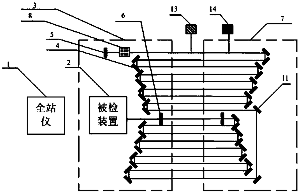
[0035] Aiming at the characteristics and detection requirements of the transmission line wire sag monitoring device based on laser distance measurement, the present invention proposes a detection device for a laser sag monitor, which uses the principle of optical reflection to realize a long-distance measurement path, and by measuring the intensity of the laser signal , frequency and phase are detected to realize laser signal weakening compensation; by analyzing the measurement error, the source of the error is found and the error value is determined; the measurement data is processed through the virtual instrument to obtain accurate detection results.

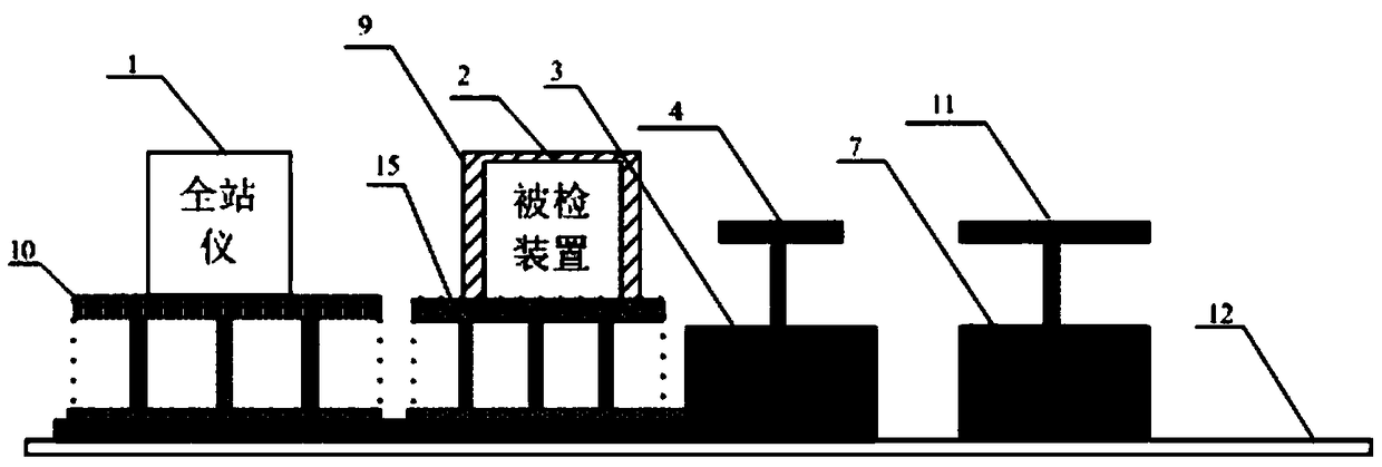
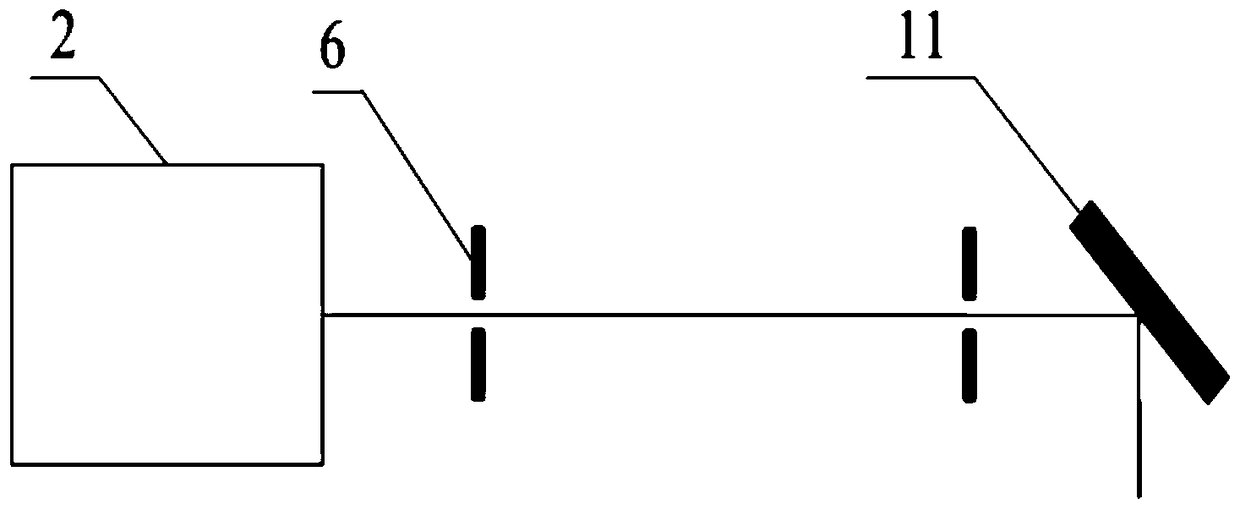
[0036] Such as figure 1 The shown test system of the present invention includes: a standard measuring instrument (total station) 1, a device under test 2, a near-end fixed platform 3, ...


PUM


Abstract

The invention provides a detection apparatus used for a laser arc sag monitor. The apparatus comprises a test system and a data processor. The test system comprises a standard measuring device and a light compensation device; the standard measuring device and the light compensation device are successively arranged on a horizontal mobile track; the data processor comprises a data input module, a data calculation module and an examination result output module; and the data processor receives and processes data input by the test system. The detection apparatus provided by the invention is simple in structure and high in measurement precision and improves the test efficiency under the condition that test detection requirements are met.

Description

technical field [0001] The invention relates to state monitoring of power transmission lines, in particular to a detection device for a laser sag monitor. Background technique [0002] Transmission line on-line monitoring devices have been widely used in power grid status management, disaster prevention and mitigation, and smart grid construction. However, the development time of transmission line on-line monitoring devices is relatively short. At present, there are generally problems such as quality and reliability of the devices, which seriously restrict The popularization and application of transmission line condition monitoring system. [0003] In order to ensure the network quality of the devices, the State Grid Corporation has established a technical laboratory for power transmission and transformation equipment condition monitoring in the China Electric Power Research Institute, and some provinces and cities have also started the construction of transmission line cond...

Claims


Application Information

Patent Timeline
Patent Type & Authority Patents(China)
IPC IPC(8): G01B11/02
CPCG01B11/02
Inventor 杨吉夏开全李茂华任西春邓元婧廖鹏王生杰谢艳丽刘岩
Owner CHINA ELECTRIC POWER RES INST
Why Eureka
Try Eureka