

Motor rotor automatic assembling machine
A technology for automatic assembly machines and motor rotors, which is applied to assembly machines, electric components, electromechanical devices, etc., can solve the problems of unguaranteed assembly quality and accuracy, increased operating costs of enterprises, and many processing and assembly procedures, etc., to achieve easy operation and Production line layout, small footprint, single and reliable action
- Summary
- Abstract
- Description
- Claims
- Application Information
AI Technical Summary
Problems solved by technology
Method used
Image

Examples
Embodiment Construction
[0033] In order to describe the technical content, structural features, achieved goals and effects of the present invention in detail, the following will be described in detail in conjunction with the embodiments and accompanying drawings.
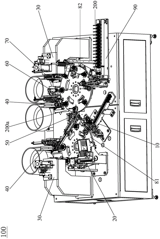
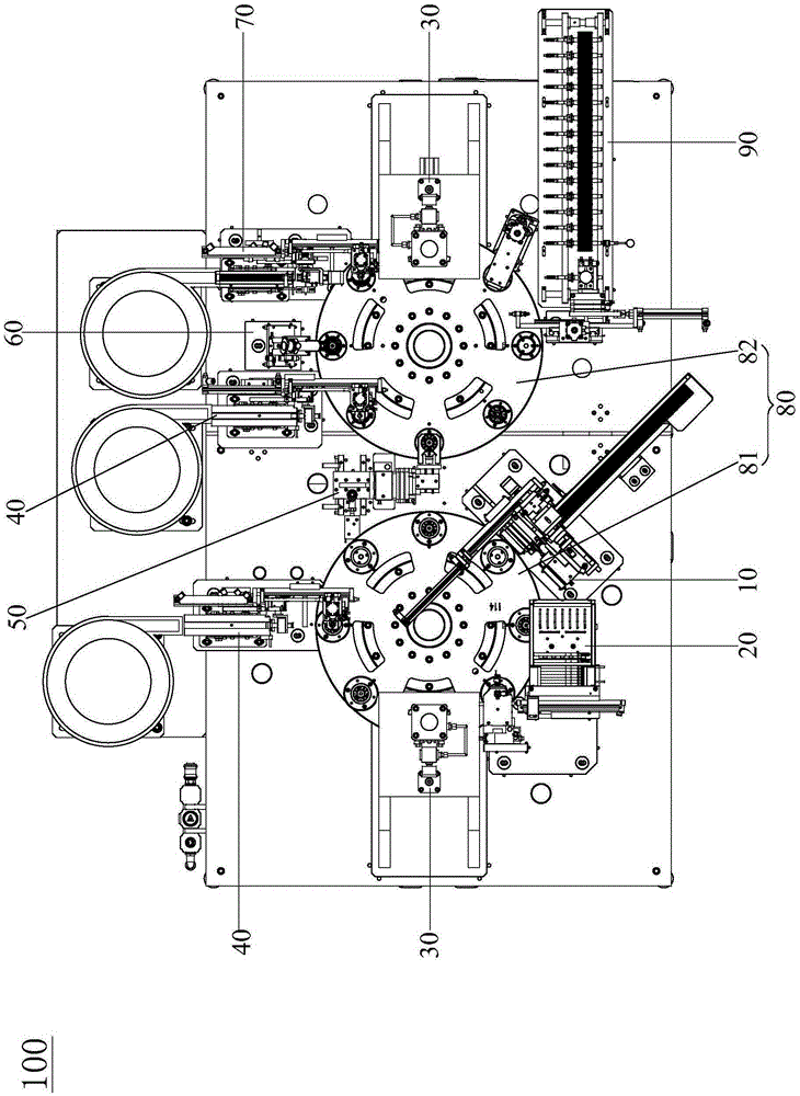
[0034] see Figure 1 to Figure 16 , the motor rotor automatic assembly machine 100 of the present invention is suitable for electrical connection with a controller (not shown in the figure), and the motor rotor automatic assembly machine 100 of the present invention is controlled by the controller to further improve the motor rotor automatic assembly machine of the present invention. 100 degree of automation, wherein the controller is an existing controller whose structure and control principle are well known in the art, so no detailed description is given here.
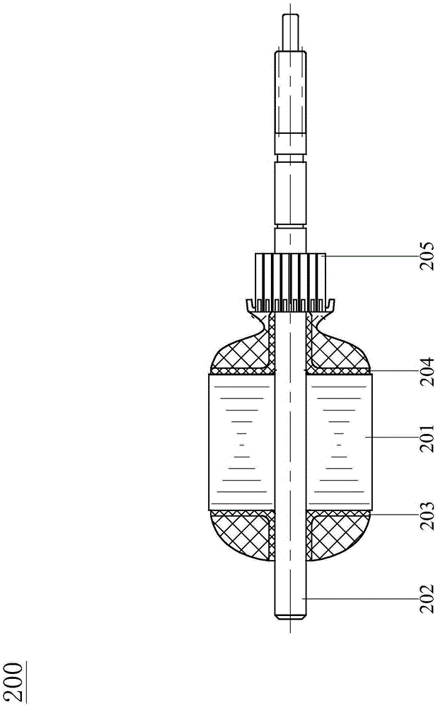
[0035] see Figure 1 to Figure 16 , The motor rotor automatic assembly machine 100 disclosed in the present invention is suitable for assembling the motor rotor 200 , the motor ...
PUM
| Property | Measurement | Unit |
|---|---|---|
| Angle | aaaaa | aaaaa |
Abstract
Description
Claims
Application Information