A mud-water pulse mixing device

A pulse mixing and muddy water technology, applied in mixers, transportation and packaging, dissolving and other directions, can solve the problems of easy failure, affecting the denitrification effect, small mixing maintenance, etc., to achieve the effect of high-efficiency mixing

Active Publication Date: 2018-03-06
刘国强
View PDF3 Cites 0 Cited by
  • Summary
  • Abstract
  • Description
  • Claims
  • Application Information

AI Technical Summary

Problems solved by technology

[0002] In the sewage treatment system, the mechanical agitator is a commonly used mixing device at present. Although the mixing efficiency is high, each agitator needs to be equipped with a separate motor, which has the disadvantages of high energy consumption, large maintenance and easy failure. In addition, A special controller is required to adjust the stirring speed, and the equipment cost is high
Compared with mechanical agitators, coarse-hole aeration and air lift pumps have the advantages of less mixing maintenance and less failure, but their mixing efficiency is not high, and a large amount of oxygen will enter the water. If they are used for agitation in anoxic areas, It will also affect the denitrification effect

Method used


Image

  • A mud-water pulse mixing device
  • A mud-water pulse mixing device

Examples


Embodiment 1

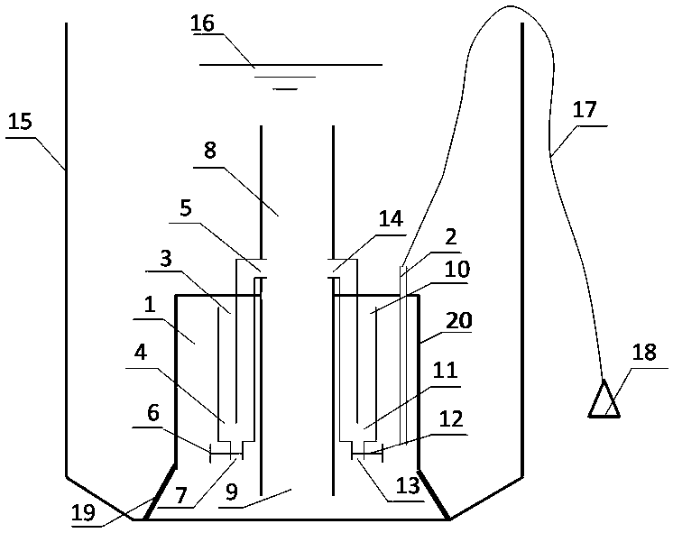
[0023] figure 1 It is a structural schematic diagram of a slurry pulse mixing device of the present invention. Such as figure 1 As shown, a mud-water pulse mixing device includes a gas-collecting hood 20 and a gas-liquid riser 8, and the gas-collecting hood 20 is connected with the gas-liquid riser 8, so that the outer wall of the gas-liquid riser 8 and the inner wall of the gas-liquid riser 20 A gas collection chamber 1 is formed between them, and the gas collection chamber 1 is provided with an air supply pipe 2, a left U-shaped air outlet pipe 4 and a right U-shaped air outlet pipe 11, the air supply pipe 2 is connected to the air pump 18 through the air pipe 17, and the lower end of the gas-liquid lift pipe 8 passes through The gas-liquid riser inlet 9 communicates with the bottom of the gas collection chamber 1; the left U-shaped air outlet pipe 4 is provided with a left air inlet 3 and a left air discharge port 5, and the gas collection chamber 1 passes through the left...

Embodiment 2

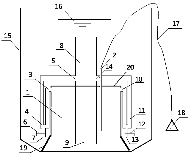
[0030] This embodiment is the second embodiment of the present invention. The difference from Embodiment 1 is that the left U-shaped air outlet pipe 4 and the right U-shaped air outlet pipe 11 are arranged outside the air collecting chamber 1 . All the other parts are identical with embodiment 1 with connection mode, as figure 2 shown. This design simplifies the internal structure of the gas collection chamber 1, thereby reducing blockage.


PUM


Abstract

A mud-water pulse mixing device, comprising an air supply device, a gas-collecting hood, a gas-liquid riser and at least one U-shaped air outlet pipe, the gas-collecting hood is connected with the gas-liquid riser so that the outer wall of the gas-liquid riser is connected to the gas-liquid riser An air-collecting chamber is formed between the inner walls, and the air-collecting chamber is connected with the gas supply device; the U-shaped air outlet pipe is provided with an air inlet and an air discharge port, and the U-shaped air outlet pipe communicates with the gas-liquid riser through the air release port, and the air inlet is close to At the top of the inner wall of the gas collecting hood, the level of the air outlet is greater than the level of the air inlet. The invention uses the gas collecting hood to collect gas, and then deflates the gas through the U-shaped gas outlet pipe, forming a powerful gas-liquid lifting effect in the gas-liquid lifting tube, realizing high-intensity, high-efficiency mixing; driven by a blower, low energy consumption and low operating costs Low; the unique U-shaped outlet pipe design makes the air collection volume controllable, and by controlling the air intake volume, the pulse mixing frequency can be controlled; the entire mixing device is under the liquid without any moving parts, no maintenance, and less failure.

Description

technical field [0001] The invention relates to the technical field of sewage treatment devices, and more specifically, to a mud-water pulse mixing device. Background technique [0002] In the sewage treatment system, the mechanical agitator is a commonly used mixing device at present. Although the mixing efficiency is high, each agitator needs to be equipped with a separate motor, which has the disadvantages of high energy consumption, large maintenance and easy failure. In addition, A special controller is required to adjust the stirring speed, and the equipment cost is high. Compared with mechanical agitators, coarse-hole aeration and air lift pumps have the advantages of less mixing maintenance and less failure, but their mixing efficiency is not high, and a large amount of oxygen will enter the water. If they are used for agitation in anoxic areas, It will also affect the denitrification effect. Contents of the invention [0003] In order to overcome at least one of...

Claims


Application Information

Patent Timeline
Patent Type & Authority Patents(China)
IPC IPC(8): B01F13/02B01F15/00B01F33/40
CPCB01F33/405B01F35/1452B01F2101/305
Inventor 刘国强
Owner 刘国强
Why Eureka
Try Eureka