Tendon-driving robot finger mechanism

A robot finger and tendon drive technology, applied in the field of robotics, can solve the problems of high machining cost, reduced finger reliability, complex transmission structure, etc., and achieve the effect of simplifying drive and transmission, simple structure, and reducing the weight of fingers

Active Publication Date: 2016-03-23
国创机器人创新中心(哈尔滨)有限公司
View PDF6 Cites 6 Cited by
  • Summary
  • Abstract
  • Description
  • Claims
  • Application Information

AI Technical Summary

Problems solved by technology

[0003] Existing robot finger joints all adopt positive and negative two-way driving methods, and the transmission structure is complex, which reduces the reliability of the fingers. However, referring to the structure of the bionic human hand, only the forward and grasping directions are used as the directions that require driving and output force. , while the reverse output force is very small and can only provide return movement, and from the perspective of the actual grasping operation needs of the manipulator, this one-way drive and reverse self-returning method can meet the needs of the grasping operation
[0004] Aluminum alloy is widely used as the material of existing manipulators, and the disadvantages are heavy weight and high machining cost

Method used


Image

  • Tendon-driving robot finger mechanism
  • Tendon-driving robot finger mechanism
  • Tendon-driving robot finger mechanism

Examples


specific Embodiment approach 1

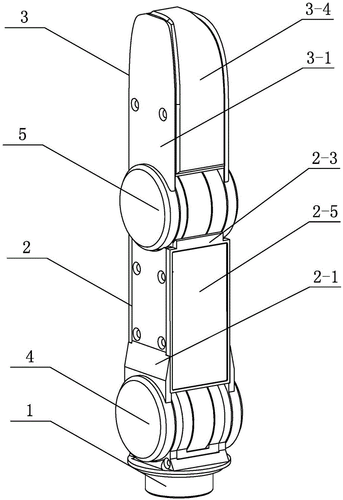
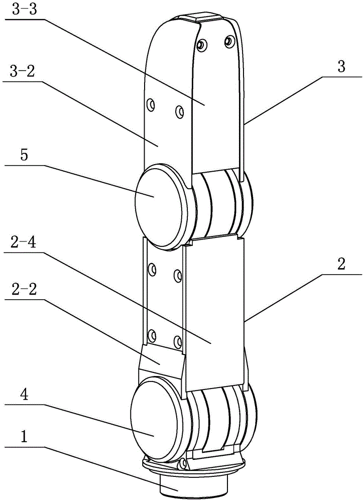
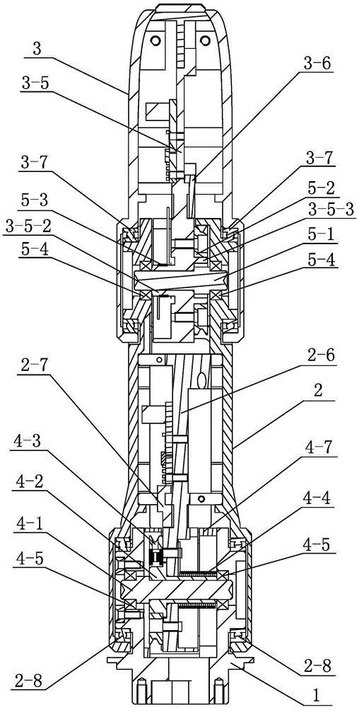
[0029] Specific implementation one: as Figure 1 to Figure 10 As shown, this embodiment describes a tendon-driven robot finger mechanism, comprising a base 1, a proximal phalanx 2, a distal phalanx 3 and two pitching joints, the two pitching joints are the base Joint 4 and end joint 5; the proximal phalanx 2 includes a proximal phalanx housing, a proximal phalangeal force transmission member 2-6 and two proximal phalangeal support bearings 2-8, and the proximal phalangeal housing includes a proximal phalanx housing. The left side plate of the phalanx 2-1, the right side plate of the proximal phalanx 2-2, the front cover plate of the proximal phalanx 2-3 and the rear cover plate of the proximal phalanx 2-4, the said rear cover plate of the proximal phalanx 2- 4 and the proximal phalanx front cover plate 2-3 are respectively connected with the proximal phalanx left side plate 2-1 and the proximal phalanx right side plate 2-2 (through screws); the upper end of the base 1 is provi...

specific Embodiment approach 2

[0033] Specific implementation two: as Figure 1 to Figure 3 As shown, in the tendon-driven robotic finger mechanism described in Embodiment 1, the base 1, the proximal phalanx shell and the terminal phalanx shell are all made of polyimide non-metallic materials.

specific Embodiment approach 3

[0034] Specific implementation three: as image 3 As shown, in the tendon-driven robotic finger mechanism described in the second embodiment, the proximal phalanx force transmission members 2-6 and the end phalangeal force transmission members 3-5 are both made of aluminum alloy materials.


PUM


Abstract

The invention discloses a tendon-driving robot finger mechanism and belongs to the technical field of robots. Tendon driving is adopted for forward joint rotation, a torsional spring force reset driving manner is adopted for backward rotation, the structure is simple and reliable, and the requirement for grasping operation can be met. A shaft sleeve of a base joint is sleeved with a base joint reset torsional spring, and the two ends of the base joint reset torsional spring are connected with a knuckle-approaching force transmission part and a base. A tail end joint tendon wheel is fixedly connected with a tail end knuckle force transmission part. The tail end joint shaft is supported on a knuckle-approaching left side plate and a knuckle-approaching right side plate through tail end joint shaft end bearings. A tail end knuckle left side plate and a tail end knuckle right side plate are supported on the knuckle left side plate and the knuckle right side plate through tail end knuckle supporting bearings. The two ends of a tail end joint reset torsional spring are connected with the tail end knuckle force transmission part and the knuckle-approaching left side plate. One end of a base joint tendon is fixedly wound in a groove wheel of a base joint tendon wheel, and the other end of the base joint tendon penetrates out of a base joint tendon sheath. One end of a tail end joint tendon is fixedly wound in the wheel groove of the tail end joint tendon wheel, and the other end of the tail end joint tendon penetrates out of a tail end joint tendon sheath. The tendon-driving robot finger mechanism is used for grabbing articles.

Description

technical field [0001] The invention relates to a finger mechanism of a robot hand, belonging to the technical field of robots. Background technique [0002] As the execution unit of the robot hand, the finger has an important influence on the hand hand such as its structure, operation ability and reliability. [0003] The existing robot finger joints are driven in both forward and reverse directions. The transmission structure is complex and the reliability of the fingers is reduced. However, referring to the structure of the bionic human hand, only the forward and grasping directions are used as the directions that require driving and output force. , while the reverse output force is very small and can only provide recovery motion, and from the perspective of the actual grasping operation needs of the manipulator, this one-way drive and reverse self-recovery method can meet the needs of the grasping operation. [0004] The material of the existing manipulator is widely us...

Claims


Application Information

Patent Timeline
Patent Type & Authority Applications(China)
IPC IPC(8): B25J15/00B25J17/00
CPCB25J15/0009B25J17/00
Inventor 刘伊威刘宏
Owner 国创机器人创新中心(哈尔滨)有限公司
Why Eureka
Try Eureka