Antenna housing structure and forming method and die thereof

A molding method and radome technology, which can be applied to the radiation unit cover and other directions, can solve the problem of not realizing the integration of the radome and the connection ring, and achieve the effects of improving connection reliability, comprehensive performance and high simulation accuracy.

Active Publication Date: 2016-03-23
SHANGHAI RADIO EQUIP RES INST
View PDF4 Cites 23 Cited by
  • Summary
  • Abstract
  • Description
  • Claims
  • Application Information

AI Technical Summary

Problems solved by technology

[0007] Patent CN104149228A "An Integrated Forming Mold and Forming Method for FRP Radome" introduces a method for forming a FRP radome with embedded round nuts. The parts are connected with the cover body by bonding in the molding process; patent CN103286957A "Preparation method of FRP, FRP radome and its preparation" introduces a preparation method of FRP radome, by adding fillers in the resin, improved Mechanical strength, reduced dielectric loss, molding process is hand lay-up process, there is no metal insert in the radome; patent CN103553696A "Manufacturing method of high temperature and ablation resistant radome cover" introduces a fiber-reinforced ceramic matrix composite The molding method of the material adopts the method of i

Method used


Image

  • Antenna housing structure and forming method and die thereof
  • Antenna housing structure and forming method and die thereof
  • Antenna housing structure and forming method and die thereof

Examples


Embodiment Construction

[0057] The present invention will be further elaborated below by describing a preferred specific embodiment in detail in conjunction with the accompanying drawings.

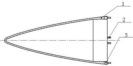
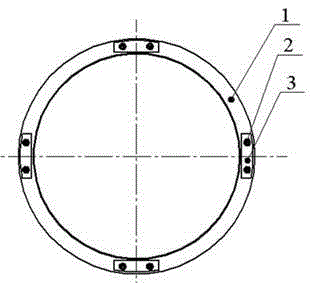
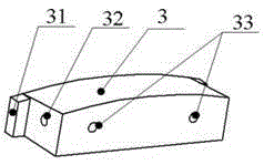
[0058] like Figure 1~2 As shown; a radome structure, which is connected to the cabin body, which includes: a cover body 1, which is made of quartz fiber reinforced silicon-containing aryne composite material, prepared by resin transfer molding (RTM); multiple embedded The insert 3 is made of low-expansion alloy steel material, and it is arranged at the root of the cover body 1. It is braided in a quartz fiber reinforcement 4 before forming, and is combined with the cover body 1 after forming. Each of the embedded inserts 3 is provided with threaded holes on the end surface; a plurality of connecting studs 2 are made of high-strength steel, and their two ends are respectively external threads, and one end of each of the connecting studs 2 is externally threaded. The threads are correspondingly fitted in the thre...


PUM


Abstract

An antenna housing structure comprises a housing body, a plurality of embedded inserts and a plurality of connection studs, wherein the housing body is made of silicon-contained quartz fiber reinforced aryne composite materials and prepared through a resin transfer molding technique; the multiple embedded inserts are made of low-expansion alloy steel materials and arranged at the root of the housing body, the embedded inserts are woven in a quartz fiber reinforcement body before being formed, the embedded inserts and the housing body are combined into a whole after the embedded inserts are formed, and a threaded hole is formed in the end face of each embedded insert; the multiple connection studs are made of high-strength steel materials, external threads are arranged at the two ends of each connecting stud, the external thread at one end of each connection stud is assembled in the threaded hole of the corresponding embedded insert of the housing body, and the external thread at the other end of each connection stud is connected with a cabin. The antenna housing structure and the forming method and the die thereof have the advantages that by the adoption of the resin transfer molding technique and the embedded inserts, the problem that transition connection between a traditional antenna housing and a cabin can only be achieved through low-expansion alloy steel connection rings is solved, the structural weight is reduced substantially, and the connection reliability is improved.

Description

technical field [0001] The invention relates to the technical field of resin-based composite material radome design and preparation, in particular to a radome structure, a forming method and a mold thereof. Background technique [0002] The radome is a key component of the guidance system. It protects the guidance system from the harsh environmental conditions during aerodynamic flight. It is also a link in the guidance control loop. It must ensure that the microwave energy of the antenna is transmitted and received without distortion. Therefore, the radome is a special product integrating aerodynamics, structure and electrical performance, which has a decisive influence on the performance of the guidance system. [0003] Quartz ceramic material is a material often used on ultra-high-speed radome at present. Compared with organic composite materials, its density is higher, and quartz ceramic material is difficult to drill or tap. The low-density low-expansion alloy steel co...

Claims


Application Information

Patent Timeline
IPC IPC(8): B29C70/48B29C33/00B29B11/00H01Q1/42
CPCB29B11/00B29C33/00B29C70/48H01Q1/42
Inventor 曾照勇沈艳陈振中蒋海峰
Owner SHANGHAI RADIO EQUIP RES INST
Why Eureka
Try Eureka