Rear flue gas system combined arrangement structure of two outlets of dust collector and double rows of induced draft fans

A technology for layout structure and induced draft fan, which is applied in lighting and heating equipment, treatment of combustion products, combustion methods, etc., can solve problems such as difficult to make full use of space, unreasonable equipment layout, and large layout to achieve compact layout , The setting is compact and the effect of reducing the floor space

Active Publication Date: 2016-03-30
CHINA ENERGY ENG GRP GUANGDONG ELECTRIC POWER DESIGN INST CO LTD
View PDF6 Cites 0 Cited by
  • Summary
  • Abstract
  • Description
  • Claims
  • Application Information

AI Technical Summary

Problems solved by technology

[0005] Based on this, in view of the above-mentioned unreasonable layout of equipment behind the dust collector, it is difficult to make full use of the space everywhere, so that the layout of the equipment behind the dust collector occupies a large area, the flue is long, and the resistance is large. The present invention proposes a dust removal Combined layout structure of the flue gas system behind the second outlet of the device and the double-row induced draft fan

Method used


Image

  • Rear flue gas system combined arrangement structure of two outlets of dust collector and double rows of induced draft fans
  • Rear flue gas system combined arrangement structure of two outlets of dust collector and double rows of induced draft fans
  • Rear flue gas system combined arrangement structure of two outlets of dust collector and double rows of induced draft fans

Examples


Embodiment Construction

[0028] Embodiments of the present invention will be described in detail below in conjunction with the accompanying drawings.

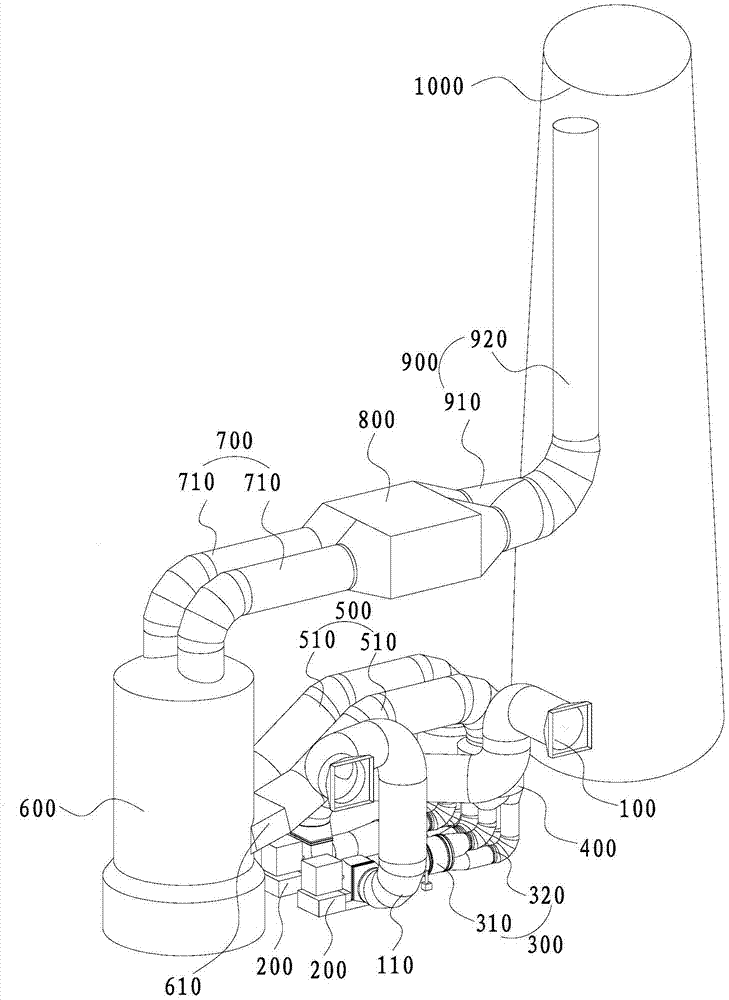
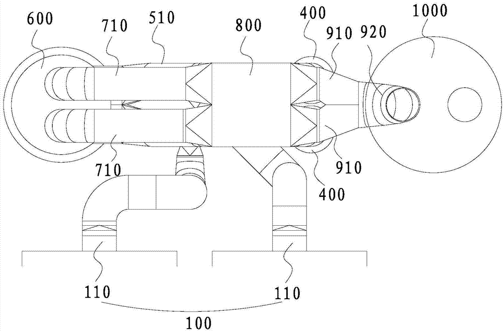
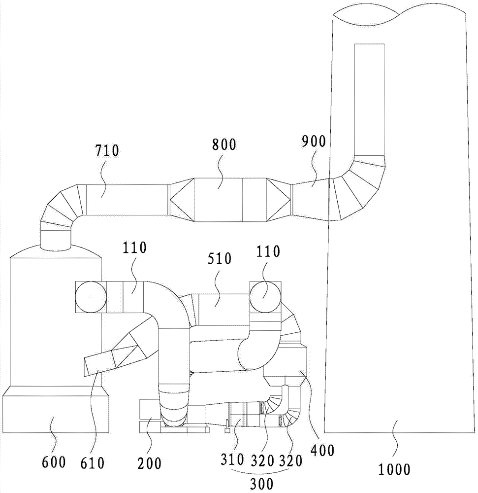
[0029] Such as figure 1 As shown, a joint layout structure of the flue gas system after the two outlets of the dust collector and the double-row induced draft fan (that is, the structure in which various equipment and pipelines are arranged behind the dust collector with two outlets), including the two outlets of the dust collector respectively The connected double-row induced draft fans 200 (including two parallel induced draft fans arranged horizontally and horizontally, with an inspection site not less than 5m wide on both sides of the two induced draft fans), the two smoke Gas waste heat recovery device 400 (that is, a row of induced draft fans is connected to a flue gas waste heat recovery device 400 ), a desulfurization absorption tower 600 connected to both flue gas waste heat recovery devices 400 , and a wet electrostatic precipitator connected...


PUM


Abstract

The invention discloses a rear flue gas system combined arrangement structure of two outlets of a dust collector and double rows of induced draft fans. The combined arrangement structure comprises the double rows of induced draft fans connected with the two outlets of the dust collector, two flue gas waste heat recovering devices correspondingly connected with the double rows of induced draft fans, a desulfurizing absorption tower connected with the two flue gas waste heat recovering devices, a wet electric dust collector connected with the desulfurizing absorption tower, and a chimney connected with the wet electric dust collector; the center lines of the double rows of induced draft fans, the two flue gas waste heat recovering devices, the desulfurizing absorption tower, the wet electric dust collector and the chimney which are sequentially connected are all positioned on the same plane; and the wet electric dust collector is arranged over the induced draft fans. The devices behind the dust collector are arranged in a space combined manner linearly, so that the devices are arranged more compactly, the occupied area is reduced, and the lengths of connecting flues are reduced.

Description

technical field [0001] The invention relates to the technical field of structural layout of a thermal power plant, in particular to a combined layout structure of the flue gas system behind the second outlet of the dust collector and the double row induced draft fan. Background technique [0002] In a coal-fired thermal power plant project, the distance from the outlet of the dust collector to the center line of the chimney is one of the important land occupation indicators. Most of the equipment in the flue gas system is arranged behind the boiler, and the layout of the front flue and the dust collector is relatively fixed. The size of the equipment layout behind the dust collector and the flue cost account for a large proportion of the initial investment of the power plant, and the resistance of the flue also directly affects the operating economy of the power plant. [0003] The main layout pattern of the equipment after the dust collector at home and abroad is basically ...

Claims


Application Information

Patent Timeline
Patent Type & Authority Applications(China)
IPC IPC(8): F23J15/02
CPCF23J15/02F23J2215/20F23J2217/102F23J2900/00
Inventor 杨劲范旭
Owner CHINA ENERGY ENG GRP GUANGDONG ELECTRIC POWER DESIGN INST CO LTD
Why Eureka
Try Eureka